
Axial relative speed indicator

a relative speed indicator and axial technology, applied in the field of speedometers, can solve the problems of requiring a certain and achieve the effect of less cognitive load of the operator and easy understanding and readabl

Inactive Publication Date: 2012-11-20
GM GLOBAL TECH OPERATIONS LLC
View PDF27 Cites 0 Cited by
  • Summary
  • Abstract
  • Description
  • Claims
  • Application Information

AI Technical Summary

Benefits of technology

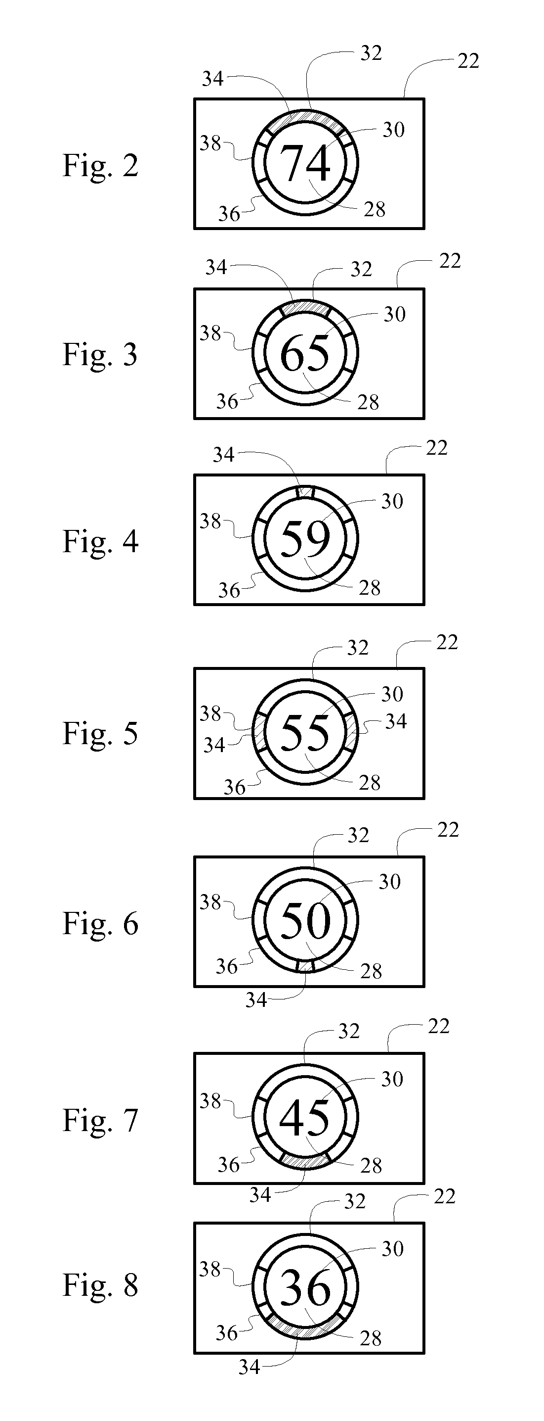
[0007]Accordingly, the speedometer of the invention displays the numeric representation of the speed of the vehicle, and graphically displays the indicator either above or below the numeric representation to visually indicate whether the speed of the vehicle is above or below the speed limit respectively. Accordingly, the subject invention provides an easily understandable and readable display the provides information on both the speed of the vehicle and the speed of the vehicle relative to the speed limit, which requires less cognitive load of the operator to understand the information.

Problems solved by technology

This requires a certain cognitive load of the operator.
However, the operator must still correlate the displayed numeric speed limit to the displayed speed of the vehicle to determine if the vehicle is traveling above or below the legal speed limit, which still requires a certain cognitive load of the operator.

Method used


Image

  • Axial relative speed indicator
  • Axial relative speed indicator
  • Axial relative speed indicator

Examples


Embodiment Construction

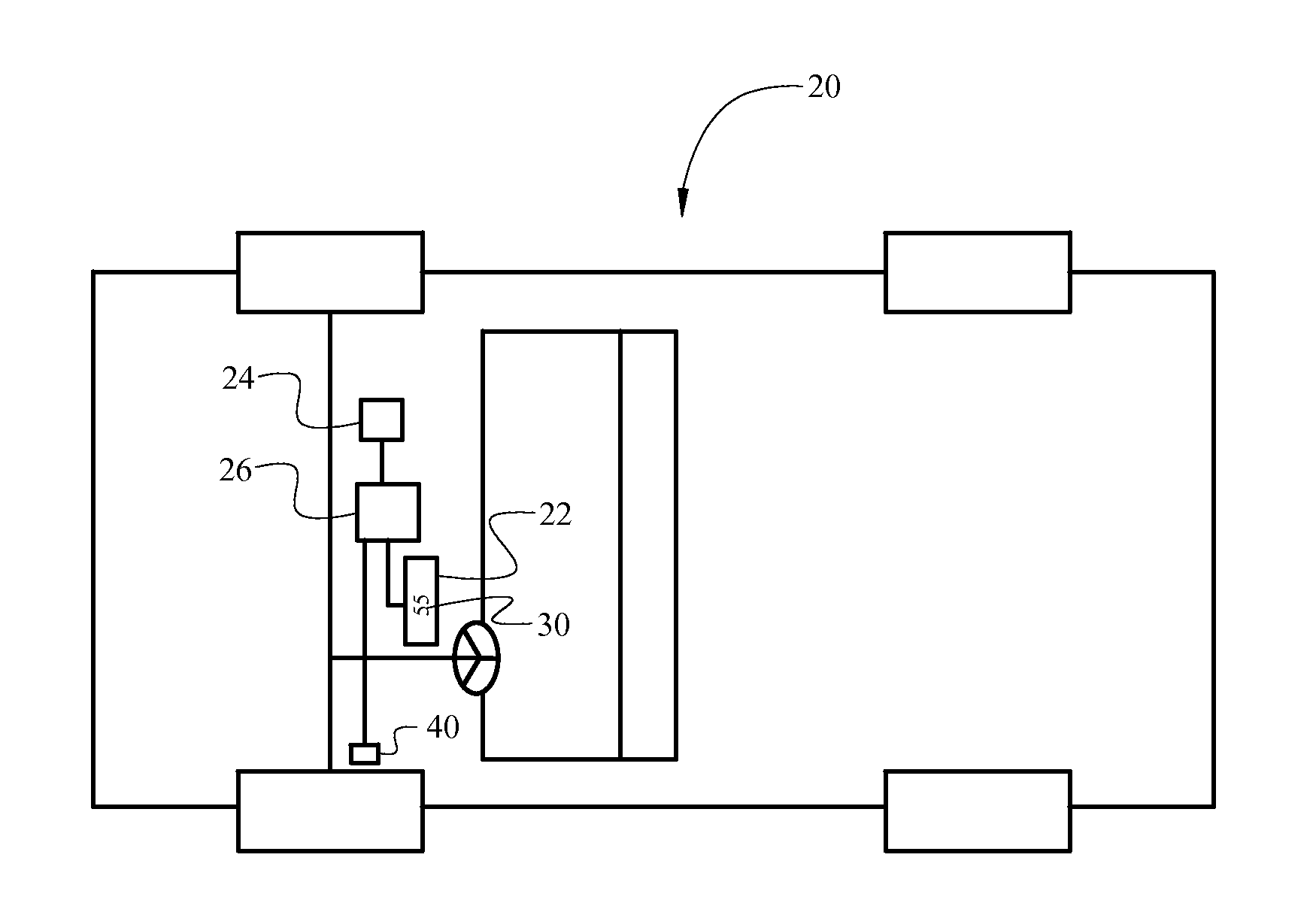
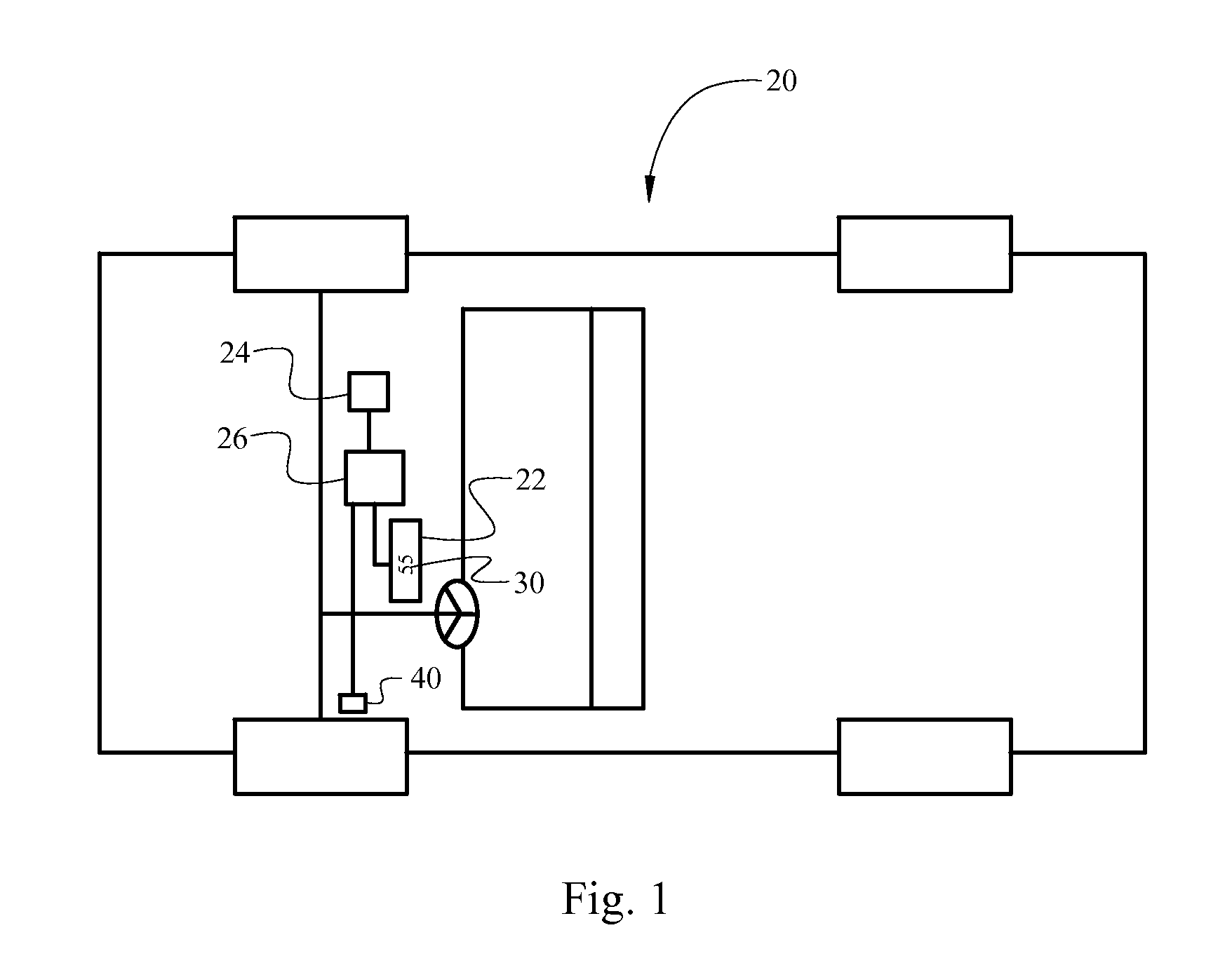
[0017]Referring to the Figures, wherein like numerals indicate corresponding parts throughout the several views, a vehicle is shown generally at 20. The vehicle 20 includes a speedometer 22, a Global Positioning Satellite (GPS) system 24, and a controller 26.

[0018]The GPS system 24 is configured for calculating a position of the vehicle 20. As is well known, the GPS system 24 triangulates the position of the vehicle 20 based upon direction signals received from orbiting satellites. The GPS system 24 may include any suitable system capable of calculating the position of the vehicle 20 based upon the received direction signals. The specific details of the GPS system 24, the operation of the GPS system 24 and the incorporation of the GPS system 24 into the vehicle 20 are well known in the art, and are therefore not described in detail herein.

[0019]The controller 26 is in communication with the speedometer 22 and the GPS system 24. The controller 26 is configured for controlling the spe...


PUM


Abstract

A speedometer displays a numeric representation of the speed of a vehicle, and further displays an indicator above the numeric representation to indicate the speed of the vehicle is above an established speed limit, or displays the indicator below the numeric representation to indicate the speed of the vehicle is below the established speed limit. The chromaticity of the indicator may be varied in relation to a magnitude of a speed differential between the speed of the vehicle and the speed limit to visually and intuitively indicate to an operator of the vehicle the magnitude of the speed differential.

Description

TECHNICAL FIELD[0001]The invention generally relates to a speedometer, and more specifically to a method of and an apparatus for indicating a speed of a vehicle relative to a speed limit.BACKGROUND OF THE INVENTION[0002]Vehicles include a speedometer to indicate a speed of the vehicle. The speedometer typically includes either a standard dial type speedometer or a speedometer. In the past, in order to determine if the speed of the vehicle is above or below a legal speed limit, an operator of the vehicle had to watch for, identify and read a posted sign along an edge of the roadway to determine the legal speed limit, and then correlate the legal speed limit to the speed displayed on the speedometer to determine if the speed of the vehicle is above or below the legal speed limit. This requires a certain cognitive load of the operator.[0003]Recently, some vehicles have been equipped to display the legal speed limit to the operator. The legal speed limit is displayed as a numeric value ...

Claims


Application Information

Patent Timeline
Patent Type & Authority Patents(United States)
IPC IPC(8): B60Q1/00
CPCB60K35/00B60K37/02B60K2350/1064B60K2370/154
Inventor RIEGELMAN, ALEXANDER THOMASLEVY, MICHAEL JOSEPH
Owner GM GLOBAL TECH OPERATIONS LLC
Learn More