Electrical distribution block apparatus and method of assembly

a technology of electric distribution block and electric receptacle, which is applied in the direction of coupling device connection, connection contact member material, engagement/disengagement of coupling parts, etc., can solve the problems of limited use and limited number of fasteners, and achieve the effect of convenient and efficient assembly and disassembly

Active Publication Date: 2012-11-27
GROUP DEKKO
View PDF12 Cites 10 Cited by
  • Summary
  • Abstract
  • Description
  • Claims
  • Application Information

AI Technical Summary

Benefits of technology

[0015]Advantageously, the present invention provides a mechanism for detachably interconnecting two components of an electrical receptacle such that the device may be easily and efficiently assembled and disassembled.

Problems solved by technology

Any number of fasteners may, however, be utilized, limited only by size constraints of the receptacle.

Method used


Image

  • Electrical distribution block apparatus and method of assembly
  • Electrical distribution block apparatus and method of assembly
  • Electrical distribution block apparatus and method of assembly

Examples


Embodiment Construction

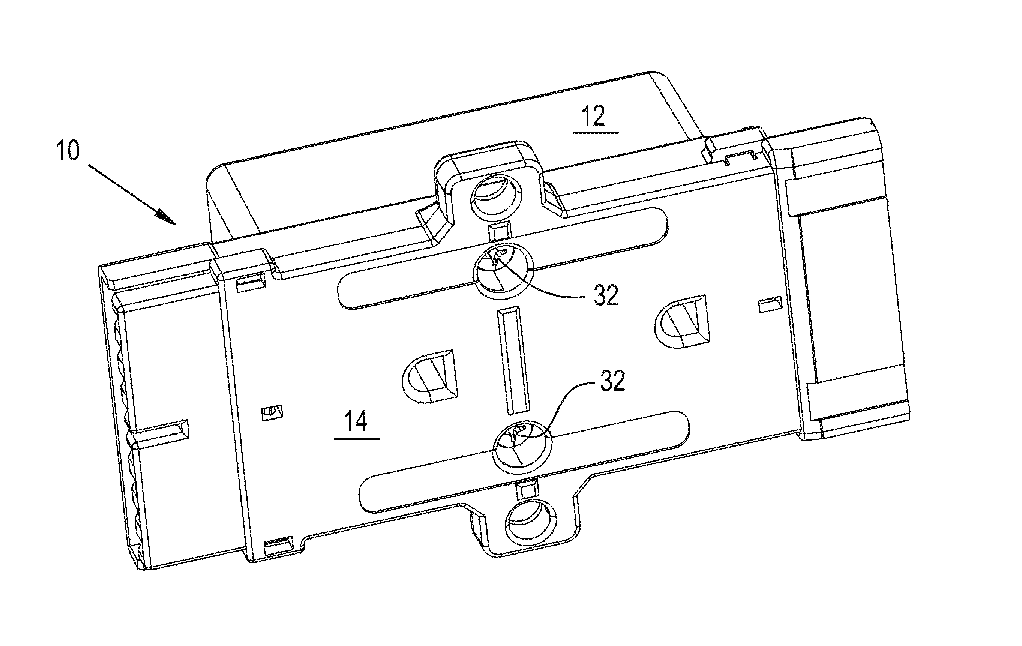
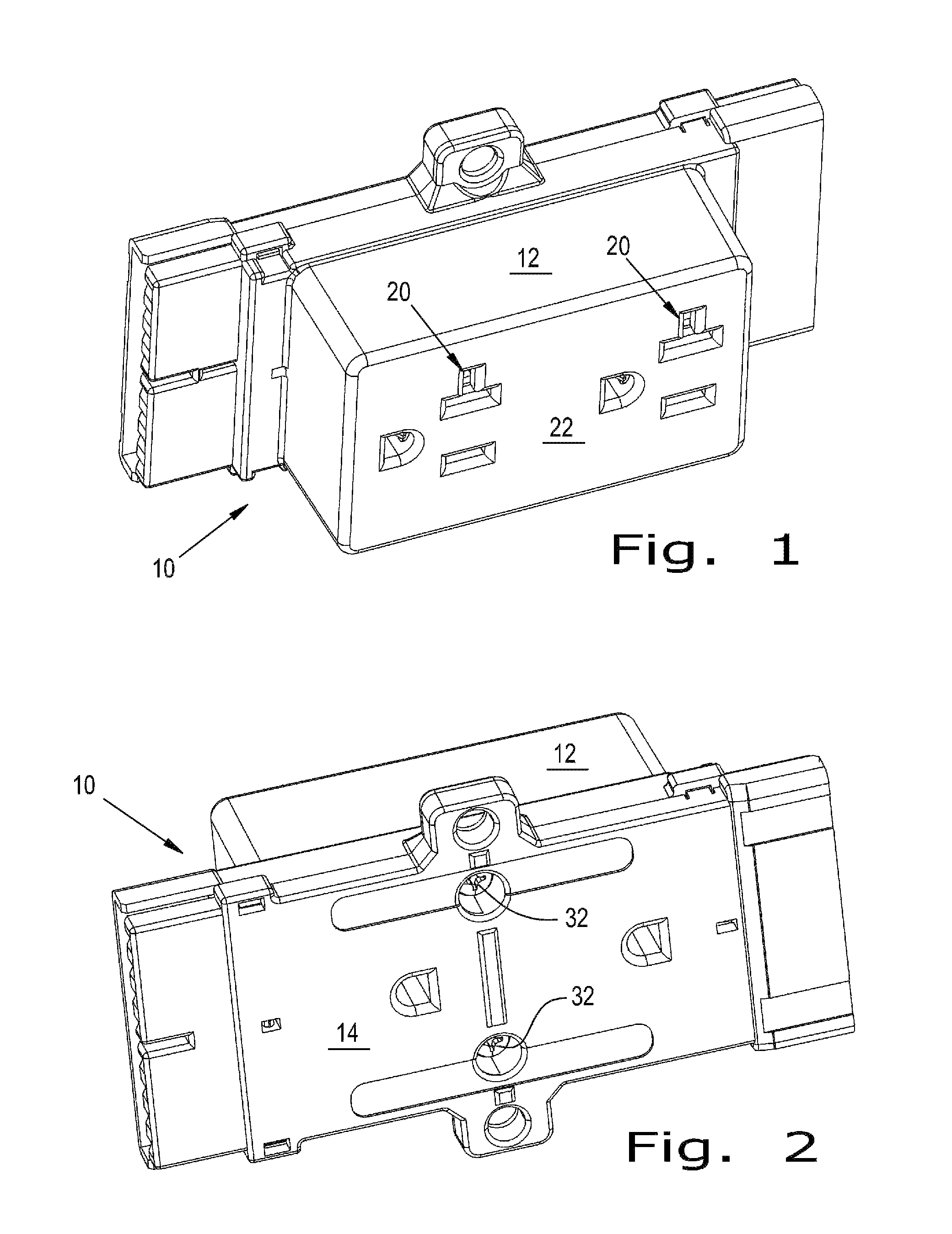
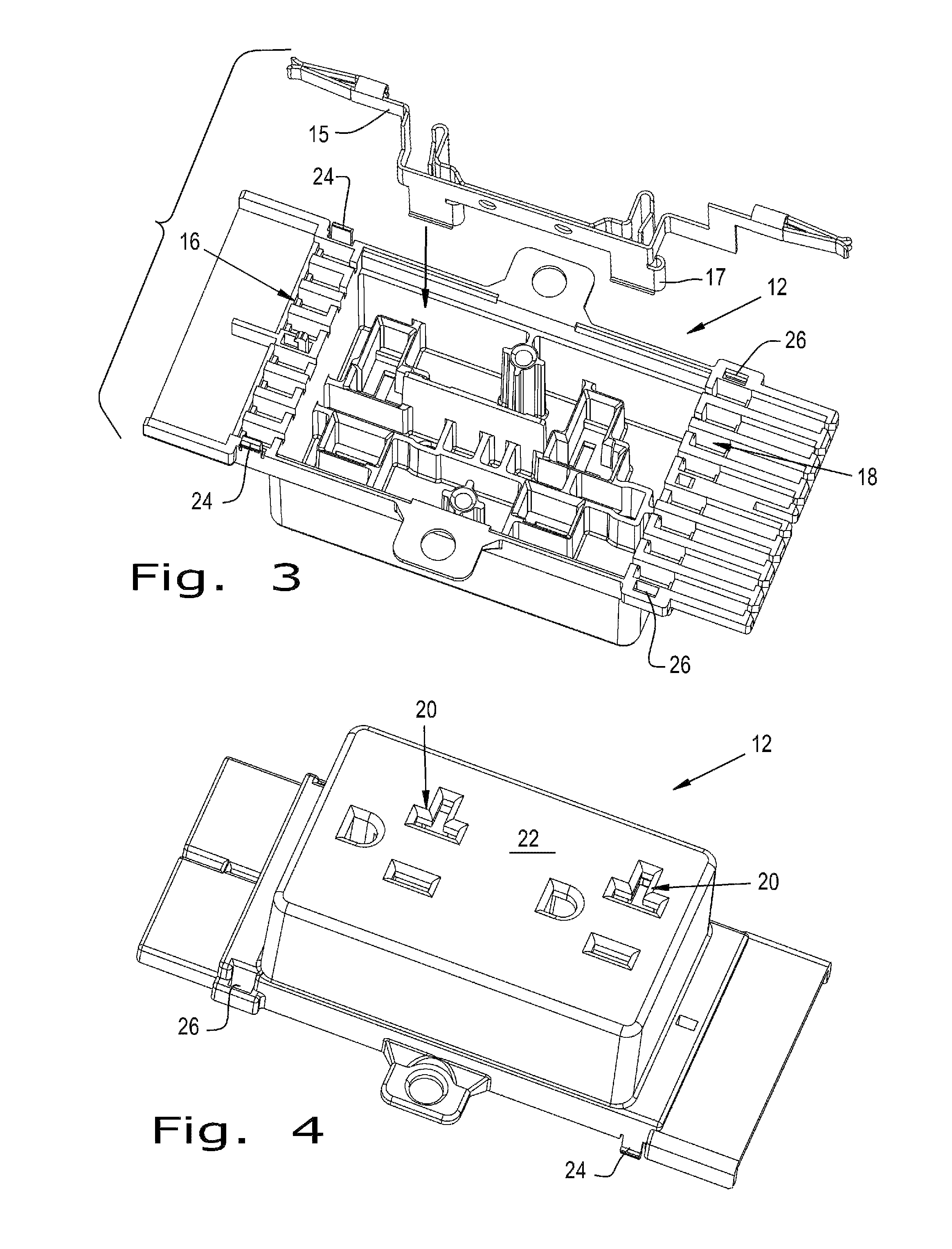
[0024]Referring now to the drawings and more particularly to FIGS. 1-6, there is illustrated an electrical distribution block 10, in the form of an electrical receptacle 10. Receptacle 10 has a first portion 12 and a mating second portion 14, which are attached together to form receptacle 10. During the assembly process electrical conductors 15 are positioned in portion 12, which can be understood by looking at FIG. 3. Only one electrical conductor 15 is shown for the sake of clarity, although typically several conductors 15 of various configurations may be utilized in receptacle 10. At least one electrical conductor 15 may extend from a positioning cavity 16 to another positioning cavity 18, and may be configured to provide electrical connections 17 proximate to openings 20 in face22.

[0025]Once the electrical conductors 15 are positioned in portion 12, portion 14 is aligned and pressed together with portion 12. Portion 12 includes protrusions 24 and receptors 26. In a similar manne...


PUM

PropertyMeasurementUnit
electricalaaaaaaaaaa
electrical conductoraaaaaaaaaa
Electrical poweraaaaaaaaaa

Abstract

An electrical receptacle includes a first portion having a face with a plurality of openings and including a first set of protrusions and a first set of receptors, the first portion being configured to receive a plurality of electrical conductors, and a second mating portion including a second set of protrusions and a second set of receptors. The first set of receptors is configured to interact with the second set of protrusions and the first set of protrusions is configured to interact with the second set of receptors to snap lock the second mating portion to the first portion and form the electrical receptacle. Further, a method is provided for assembling and disassembling an electrical receptacle.

Description

CROSS REFERENCE TO RELATED APPLICATIONS[0001]This is a non-provisional application based upon U.S. provisional patent application Ser. No. 61 / 310,470, entitled “ELECTRICAL DISTRIBUTION BLOCK APPARATUS AND METHOD OF ASSEMBLY”, filed Mar. 4, 2010, which is incorporated herein by reference.BACKGROUND OF THE INVENTION[0002]1. Field of the Invention[0003]The present invention relates to an electrical distribution block apparatus, and, more particularly, to an electrical receptacle.[0004]2. Description of the Related Art[0005]Electrical power is distributed by networks of electrical conduits that terminate in electrical outlet boxes where the electrical power is accessed. Power from the electrical conduits is connected in the outlet boxes to electrical receptacles positioned on the boxes. The electrical receptacles have slots and apertures for receiving prongs of appliances and to connect to other electrical devices. Such networks are used in residential and commercial construction, as we...

Claims


Application Information

Patent Timeline
Patent Type & Authority Patents(United States)
IPC IPC(8): H01R4/60
CPCH01R13/62H01R43/20H01R24/00Y10T29/49208H01R13/506H01R13/514H01R24/78
Inventor RINER, RAYMOND H.PLATTNER, BRADLEY
Owner GROUP DEKKO
Why Eureka
Try Eureka