Method for manufacturing medium on which information is recorded in pit pattern

a manufacturing medium and information technology, applied in the field of manufacturing a medium on which, can solve the problems of complicated manufacturing process, possible removal of pits and projections of the layer, etc., and achieve the effect of prolonging the preservation period

Inactive Publication Date: 2012-12-04
FUJIFILM CORP
View PDF13 Cites 1 Cited by
  • Summary
  • Abstract
  • Description
  • Claims
  • Application Information

AI Technical Summary

Benefits of technology

[0004]However, in the conventional manufacturing method as described above, the pits and projections are formed in the layer provided on the glass substrate. Therefore, over a long period of storage, the layer having the pits and the projections would possibly become easily stripped off. It would thus be desirable that a fine pattern of pits and projections be formed directly in the substrate of inorganic matter so that a longer period of preservation can be achieved. It is also to be noted that the conventional manufacturing method requires several steps of the coating of a solution, the application of a mold, the primary burning operation, and the secondary burning operation and removal of organic components, which should render the manufacturing process complicate.
[0008]According to the above-described embodiment of the present invention, first, a recording material layer is formed over a substrate, and then a plurality of holes are formed in the recording material layer by application of condensed light to this recording material layer. Thereafter, the recording material layer having the plurality of holes formed therein is used as a mask for an etching process, to thereby directly form the pits corresponding to the plurality of holes. With this configuration, a pattern of pits and projections can easily be formed on the surface of the substrate merely by following the steps of forming the recording material layer, application of light and etching.

Problems solved by technology

Therefore, over a long period of storage, the layer having the pits and the projections would possibly become easily stripped off.
It is also to be noted that the conventional manufacturing method requires several steps of the coating of a solution, the application of a mold, the primary burning operation, and the secondary burning operation and removal of organic components, which should render the manufacturing process complicate.

Method used


Image

  • Method for manufacturing medium on which information is recorded in pit pattern
  • Method for manufacturing medium on which information is recorded in pit pattern
  • Method for manufacturing medium on which information is recorded in pit pattern

Examples


example

[0114]One example implemented with which the advantageous effects of the present invention have been confirmed will be described below.

[0115]In the example, a substrate similar to that of the above-described embodiment was manufactured. The substrate was formed like a disc, and a dye-containing layer (recording material layer) having a thickness of approximately 100 nm and a barrier layer were formed thereon as an etching mask, and RIE was carried out.

[0116]Details are as follows.
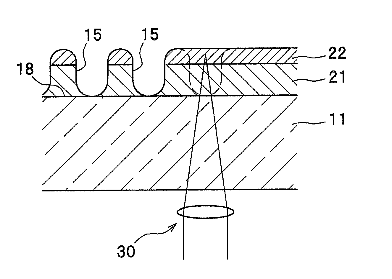
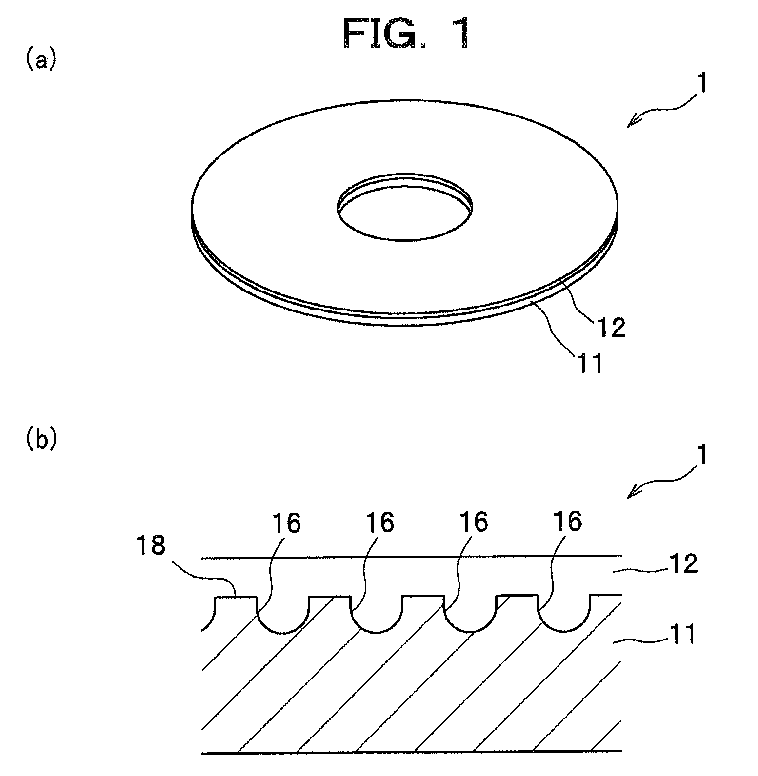
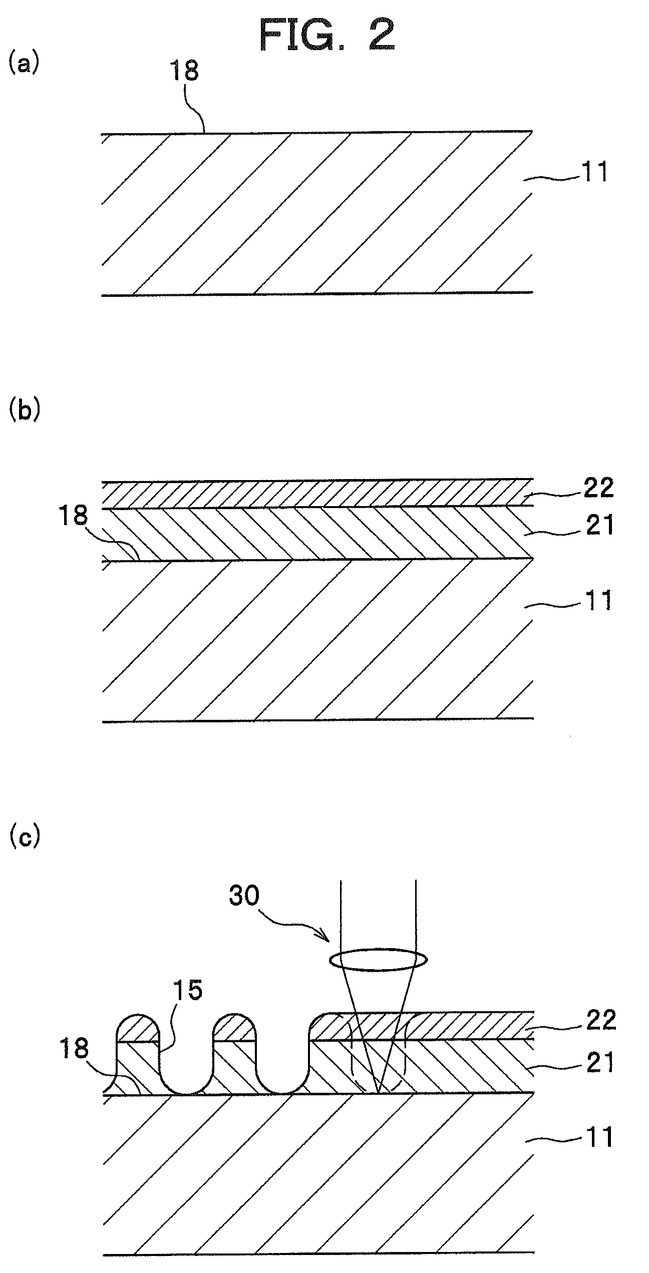
[0117]Substrate

[0118]

Material:SiliconThickness: 0.5 mmOuter diameter:101.6 mm (4 inch)Inner diameter:  15 mm

[0119]Dye-Containing Layer (Recording Material Layer)

[0120]2 g of the dye-containing material given by the following chemical formula was dissolved in 100 ml of TFP (tetrafluoropropanol) solvent, and the resulting solution was spin coated. In this spin-coating process carried out with a dispense-start rotation speed of 500 rpm and a dispense-end rotation speed of 1,000 rpm, a coating liquid was dispen...


PUM

PropertyMeasurementUnit
oscillation wavelengthaaaaaaaaaa

Abstract

A method by which depressions and projections (pit pattern) can be formed directly and easily in a substrate made of inorganic material is provided. A method for forming a medium on which information is recorded in a pit pattern comprises the steps of: forming a recording material layer over a substrate made of inorganic material wherein the recording material layer is of a thermally deformable heat mode recording material; forming a plurality of holes by application of condensed light to the recording material layer; and forming a plurality of pits in the substrate wherein the plurality of pits corresponding to the plurality of holes are etched by using as a mask the recording material layer in which the plurality of holes are formed.

Description

TECHNICAL FIELD[0001]This invention relates to a method for manufacturing a medium on which information is recorded in a pit pattern.BACKGROUND ART[0002]Among conventionally known methods for manufacturing a medium such as an optical disc on which information is recorded in an optically retrievable manner is a manufacturing method as disclosed in Japanese Laid-Open Patent Application, Publication (JP-A) No. 3-40244. In this technique, first, a glass substrate made of glass that is inorganic matter is coated with a solution made of metal alcoholate, water, hydrochloric acid, alcohol, and other components, to form a predetermined layer. Then, while a mold made of plastic is being applied to this layer, a primary burning operation is carried out at 60-120 degrees centigrade.[0003]Thereafter, the glass substrate is separated from the mold, and subjected to a secondary burning operation at 250-400 degrees centigrade to remove organic components such as a solvent, an additive, etc., so th...

Claims


Application Information

Patent Timeline
Patent Type & Authority Patents(United States)
IPC IPC(8): B32B3/02
CPCB41M5/24G11B7/261Y10T428/21
Inventor USAMI, YOSHIHISAWATANABE, TETSUYA
Owner FUJIFILM CORP
Why Eureka
Try Eureka