
Flotation device for rescue apparatus and method of use

a technology for flotation devices and rescue equipment, applied in the field of aquatic safety devices, can solve problems such as the belief that there is no product specifically designed to address such emergencies, and achieve the effect of optimizing the buoyancy of the flotation device and facilitating the stabilization of the injured person

Inactive Publication Date: 2012-12-11
CYNAMON SAM
View PDF12 Cites 12 Cited by
  • Summary
  • Abstract
  • Description
  • Claims
  • Application Information

AI Technical Summary

Benefits of technology

[0011]In use to stabilize an injured person in an aquatic environment, the flotation device is readied for use by connecting the buoyant structure to the support portion, the injured person in the body of water is placed onto the support portion, and fluid is directed into the hollow space of each container until the buoyant structure is capable of providing buoyancy for the injured person when placed onto the support portion. Fluid may be directed into the container(s) before, during and / or after the injured person is placed onto the support portion. Then, the pressure of the fluid in the hollow space of each container, i.e., the buoyancy force, is preferably adjusted relative to, for example, a size of the injured person and / or conditions of the aquatic environment to thereby optimize the buoyancy of the flotation device and facilitate an easier stabilization of the injured person in consideration of the stabilization conditions then existing.

Problems solved by technology

To date, there is not believed to be any product specifically designed to address such emergencies in consideration of the relatively large number of variables that affect the use of a backboard or other type of rescue apparatus in the aquatic environment.

Method used


Image

  • Flotation device for rescue apparatus and method of use
  • Flotation device for rescue apparatus and method of use
  • Flotation device for rescue apparatus and method of use

Examples


Embodiment Construction

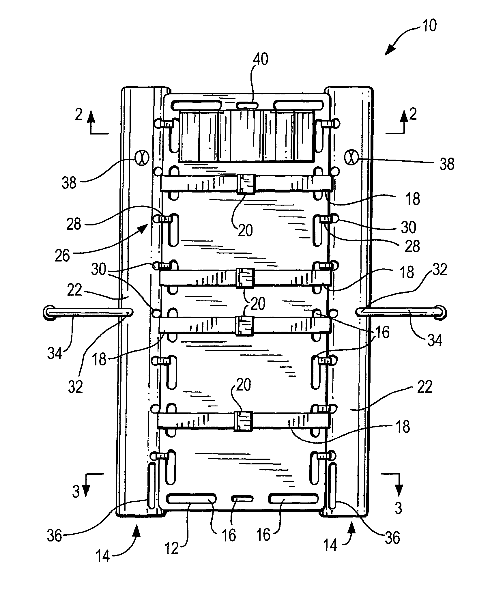
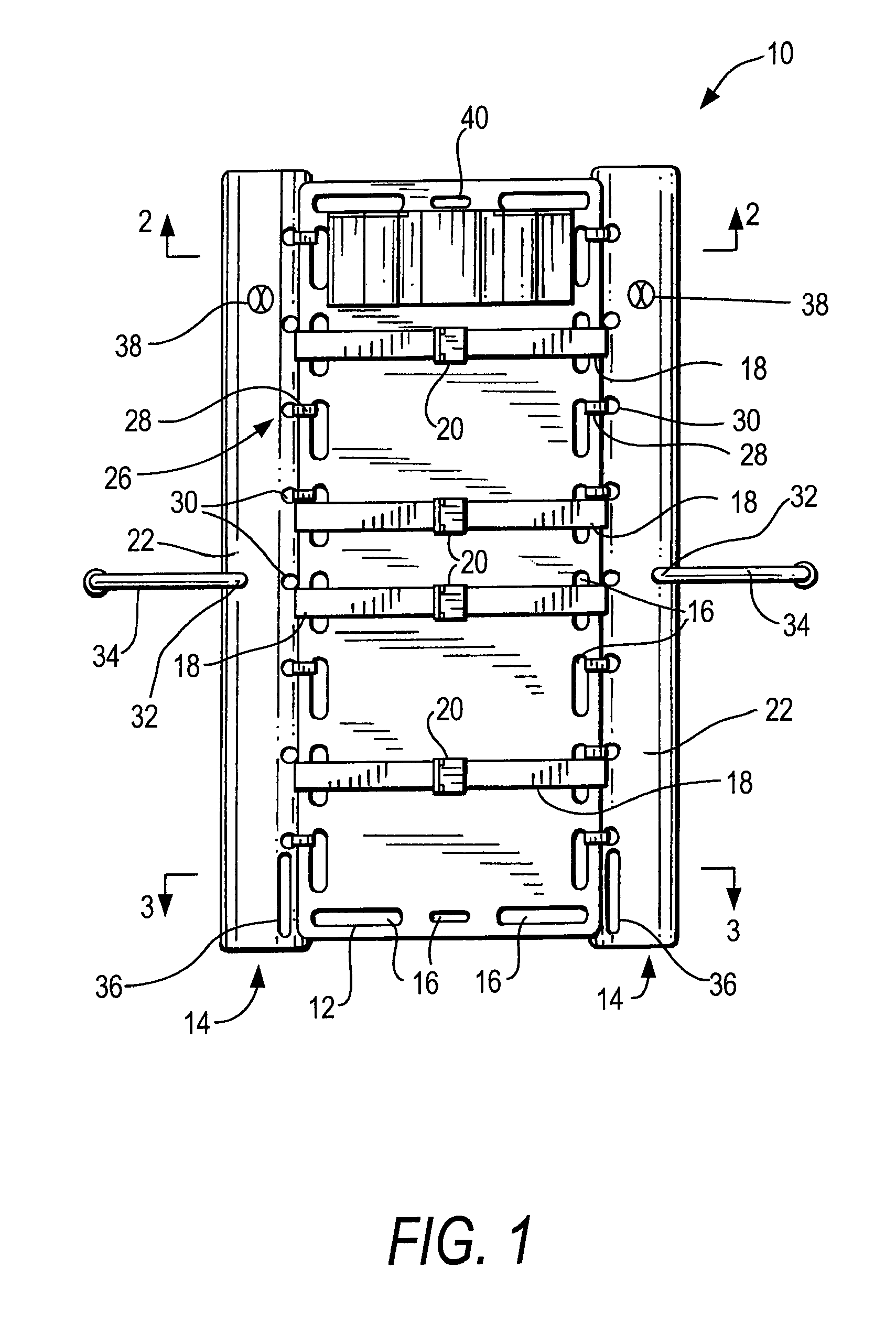
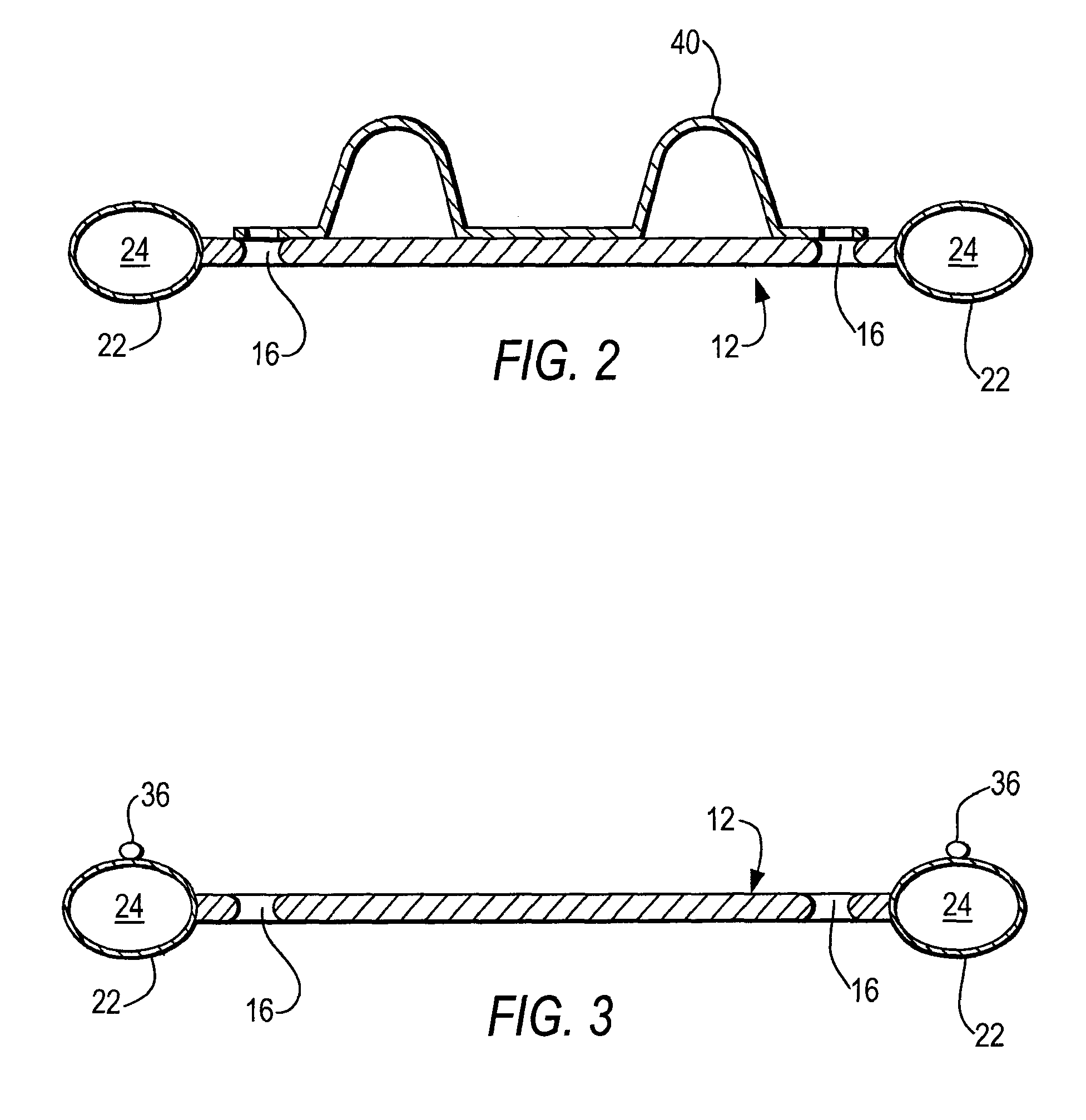
[0018]Referring to the accompanying drawings wherein like reference numerals refer to the same or similar elements, FIG. 1 is a top view of a flotation device 10 in accordance with the invention when used with a backboard as an example of a rescue apparatus that can be used in accordance with the invention. Flotation device 10 includes a backboard portion 12 and a buoyant structure 14 that is connected to the backboard portion 12 and provides buoyancy to the backboard portion 12, with or without an injured person placed thereon. Alternatively, the flotation device may be considered to comprise only the buoyant structure 14 that is attached to an existing backboard (or other piece of rescue equipment), and not the backboard portion per se. In this case, the flotation device can be designed to connect to multiple and different types of rescue equipment.

[0019]Backboard portion 12 may also be considered as a spineboard as this term is understood to those skilled in the art in that it en...


PUM


Abstract

Flotation device for rescue apparatus includes a support portion onto which an injured person is placed, and a buoyant structure connected to the support portion to provide buoyancy for the support portion. The buoyant structure includes one or more fluid containers each attached to the support portion by, for example, straps. At least one pressure regulating mechanism is integrated into or onto a surface of each container and functions to vary pressure of fluid in the hollow space of the container, and may include inflation mechanisms that enable controlled inflow of fluid into the hollow space of the containers, and deflation or pressure release mechanisms that enable controlled outflow of fluid from the hollow space of the containers,

Description

CROSS REFERENCE TO RELATED APPLICATION[0001]This application claims priority under 35 U.S.C. §119 of U.S. provisional patent application Ser. No. 61 / 210,204 filed Mar. 16, 2009, the disclosure of which is incorporated by reference herein.FIELD OF THE INVENTION[0002]The present invention relates generally to an aquatic safety device and more particularly to a device for use in stabilizing a potentially injured person in a body of water and enabling transport of the person from the body of water to dry land while in a stabilized state, and possible further transport of the person as needed.[0003]The present invention also relates to a method for stabilizing a person in a body of water and enabling transport of the person from the body of water to dry land while in a stabilized state, and which also enables further transporting of the person as needed.BACKGROUND OF THE INVENTION[0004]All nationally recognized organizations, including the American Red Cross, the Young Men's Christian As...

Claims


Application Information

Patent Timeline
Patent Type & Authority Patents(United States)
IPC IPC(8): B63C9/00
CPCA61G1/01B63C9/04A61G1/044
Inventor CYNAMON, SAM
Owner CYNAMON SAM
Learn More