Built-in anti-floating anchor blocking structure used in foundation mat for deep-well dewatering well and construction method

A technology for anti-floating anchor rods and foundation bottom plates, which is applied in infrastructure engineering, protection devices, buildings, etc., can solve the problems of inability to repair, long time for sealing and welding, and corrosion of steel threads, so as to improve the anti-floating performance. , Improve waterproof effect, good waterproof effect

Active Publication Date: 2015-12-23
CITIC GUOAN CONSTR GRP CO LTD
View PDF9 Cites 27 Cited by
  • Summary
  • Abstract
  • Description
  • Claims
  • Application Information

AI Technical Summary

Problems solved by technology

[0003] At present, the traditional construction method is to backfill gravel concrete to the foundation cushion level immediately after the groundwater in the dewatering well is drained, and at the same time use expansive concrete with a light strength grade higher than the foundation concrete to pour to the top surface of the foundation. The disadvantage of the construction method is that it will Construction joints occur at the head of the dewatering well, which brings hidden dangers of water leakage and cannot be repaired; or use steel pipes to extend the dewatering well, pass through the foundation floor, and weld the water-stop flange on the outside of the steel pipe. The shortcoming of the construction method is that the plugging and welding time is long, and it is difficult to plug the precipitation well with a large water output
[0004] Furthermore, in order to improve the engineering quality of the dewatering well plugging construction, there are many new types of dewatering well plugging technologies, such as a dewatering well plugging system (ZL: 201120242057.4), which uses steel pipes to extend the dewatering well and pass through For the foundation floor, the outer side of the steel pipe is welded with the water-stop flange, and at the same time, welding threaded fasteners are added to the steel pipe. When sealing, the threaded blocking plate is directly used for sealing. Although the sealing speed is relatively fast, the connection strength between the steel pipe and the dewatering well Insufficient, cracks are easy to occur when the building is unevenly settled, and the steel thread is easy to corrode, and the durability is poor; another example is a deep foundation pit dewatering well sealing structure (ZL: 201320158546.0), which extends the steel pipe into the dewatering well , using fixtures and flange sealing, and setting waterproof layer and waterproof membrane at the same time, although it has high sealing performance with the foundation bottom plate, it will cause overall blockage when the groundwater level is high and the buoyancy is too large Quality hazards such as structural lifting
In addition, in the plugging construction of dewatering wells, some auxiliary plugging devices are often used for plugging construction, but there are defects such as complex structure, high cost, and narrow application range.
[0005] To sum up, although the existing plugging structure of dewatering wells can achieve a relatively ideal plugging effect, there are still room for improvement in terms of the durability of the plugging structure, construction efficiency, anti-floating performance, and economic benefits.

Method used


Image

  • Built-in anti-floating anchor blocking structure used in foundation mat for deep-well dewatering well and construction method
  • Built-in anti-floating anchor blocking structure used in foundation mat for deep-well dewatering well and construction method
  • Built-in anti-floating anchor blocking structure used in foundation mat for deep-well dewatering well and construction method

Examples


Embodiment Construction

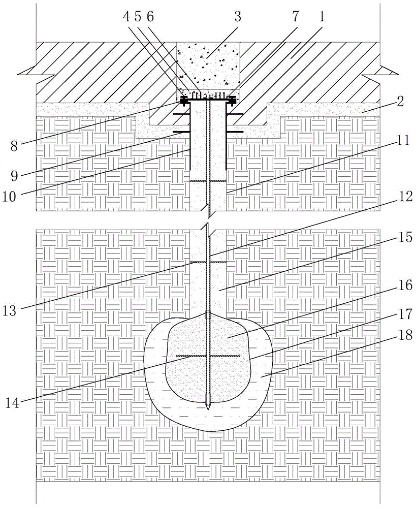
[0034] In this embodiment, the technical requirements for the construction of the base plate and the cushion, the technical requirements for welding construction, the ratio of the high-pressure grouting of the bladder, etc. will not be described in detail, and the construction of the anti-floating anchor plugging structure built in the deep well dewatering well involved in the present invention will be focused on implementation.

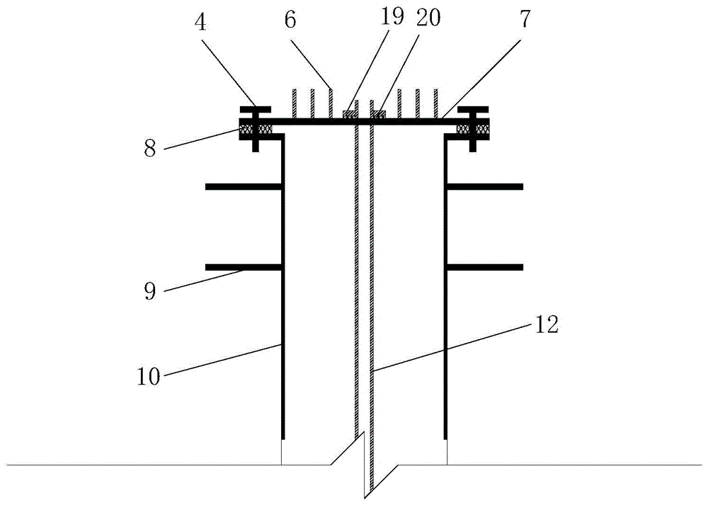
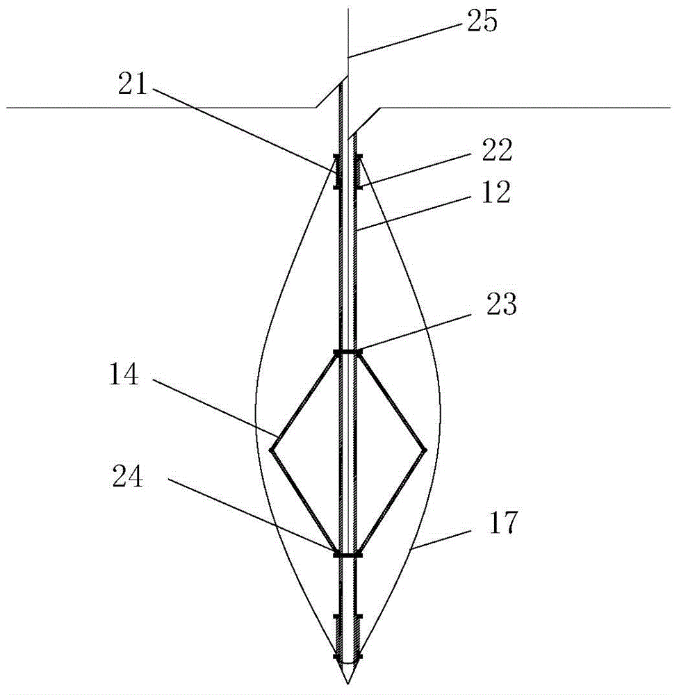
[0035] figure 1 It is a schematic diagram of the plugging structure of the built-in anti-floating anchor rod in the deep well dewatering well of the foundation floor of the present invention, figure 2 It is a schematic diagram of the connection between the steel casing and the plugging steel plate in the present invention, image 3 It is a schematic diagram of the connection between the capsule bag and the rod body in the capsule type anti-floating anchor rod of the present invention. refer to figure 1 The deep well dewatering well shown has a bu...


PUM


Abstract

The invention relates to a built-in anti-floating anchor blocking structure used in a foundation mat for a deep-well dewatering well. A steel sleeve is arranged on a rainfall wellhead. The bottom of a rainfall well forms a body expansion soil end through expansion holes. A bag type anti-floating anchor rod is arranged in the well. An expansion end plate is arranged in an anchor rod bag. Annular positioning rebars are arranged on the bag type anti-floating anchor rod. The anchor rod bag forms a grouting body expansion anti-floating end through high-pressure pouring after being inserted into the body expansion soil. The upper end of the anchor rod is anchored after penetrating a blocking steel plate. Connection rebars are connected to the top face of the blocking steel plate in a welding manner. The bottom face of the blocking steel plate is provided with a waterproof rubber gasket. The blocking steel plate is connected with a steel sleeve connection steel plate through bolts. The top face of the blocking steel plate sequentially comprises a waterproof concrete layer and a post-poured concrete sealing body. According to the deep-well dewatering well built-in anti-floating anchor blocking structure, by means of the built-in anti-floating anchor rod manner, the wellhead blocking quality can be guaranteed while the situation that the rainwater wellhead is destroyed due to the fact that underground water comes up to the top during the later period is reduced, and the built-in anti-floating anchor blocking structure has better economic and technical benefits.

Description

technical field [0001] The invention relates to a built-in anti-floating bolt plugging structure and construction method of a deep well dewatering well on a foundation floor. The utility model belongs to the field of foundation treatment and is suitable for the plugging and treatment project of the dewatering well of the building foundation. Background technique [0002] With the limitation of above-ground development space in cities, the utilization rate of underground space is increasing year by year and deepening. Therefore, deep foundation pits will be excavated during a large number of building constructions. In the construction of deep foundation pits, it is often encountered that dewatering wells are set in the basement of the permanent structure floor. situation. In most cases, in order to meet the requirements of the construction site, the dewatering well needs to be sealed after the construction of the bottom plate is completed. Therefore, it is inevitable for the...

Claims


Application Information

Patent Timeline
Patent Type & Authority Applications(China)
IPC IPC(8): E02D19/16E02D31/12
Inventor 王新泉
Owner CITIC GUOAN CONSTR GRP CO LTD
Why Eureka
Try Eureka