Underwater enclosure apparatus and method for constructing the same

a technology of enclosure and enclosure device, which is applied in the field of enclosure apparatus, can solve the problems of high buoyancy, lack of inherent strength and robustness, and the inability to meet the requirements of underwater conditions, and achieve the effect of reducing the curing temperature of resin

Inactive Publication Date: 2006-07-20
COOPER CAMERON CORP
View PDF9 Cites 27 Cited by
  • Summary
  • Abstract
  • Description
  • Claims
  • Application Information

AI Technical Summary

Benefits of technology

[0025] The use of a continuous, substantially void-free resinous phase as a structural filler allows a very strong, pressure-resistant apparatus to be provided. While the density of the filler is higher than of the fillers discussed above, the continuous, void-free phase provides virtually a complete transfer of stress from the outer shell to the inner shell, thus sharing the stresses induced by hydrostatic pressure.
[0026] The filler is preferably a resin, especially a polyester resin,...

Problems solved by technology

One significant disadvantage of syntactic foam is that the material, while having a low density and thus a high buoyancy, lacks inherent strength and robustness.
While widely used, syntactic foam buoyancy devices suffer a number of significant drawbacks.
First, as noted above, the syntactic foam itself is inherently weak and easily damaged.
The need to provide the foam with some form of reinforced coating or covering increases the complexity of the method of manufacturing the buoyancy device, the overall time of manufacture and the overall cost of the device.
Further, syntactic foam has limits as to its application.
The casting process is limited in terms of the overall size of the foam unit and it is not possible to easily cast the larger units required in certain underwater operations.
This again adds to the com...

Method used


Image

  • Underwater enclosure apparatus and method for constructing the same
  • Underwater enclosure apparatus and method for constructing the same
  • Underwater enclosure apparatus and method for constructing the same

Examples


examples

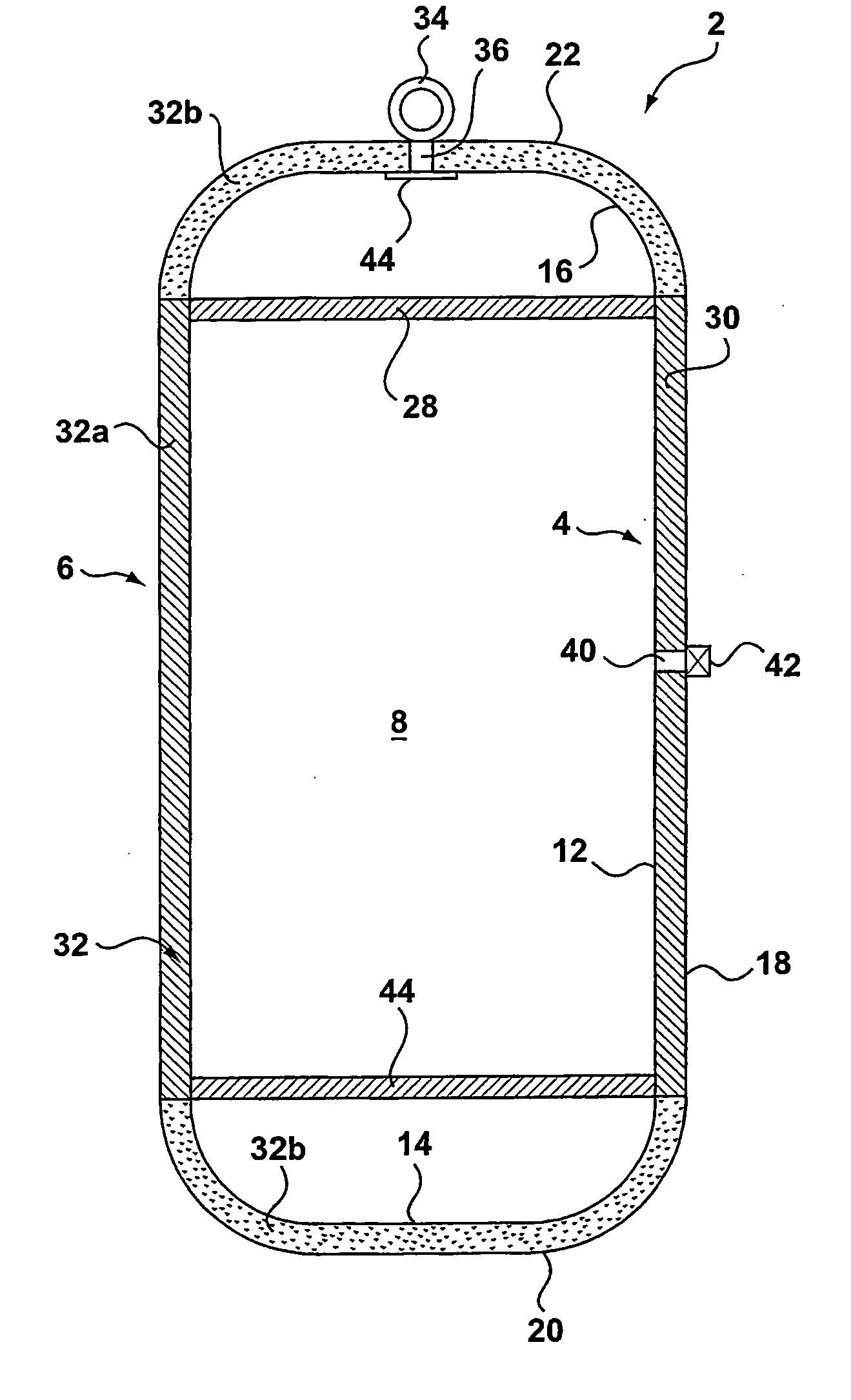
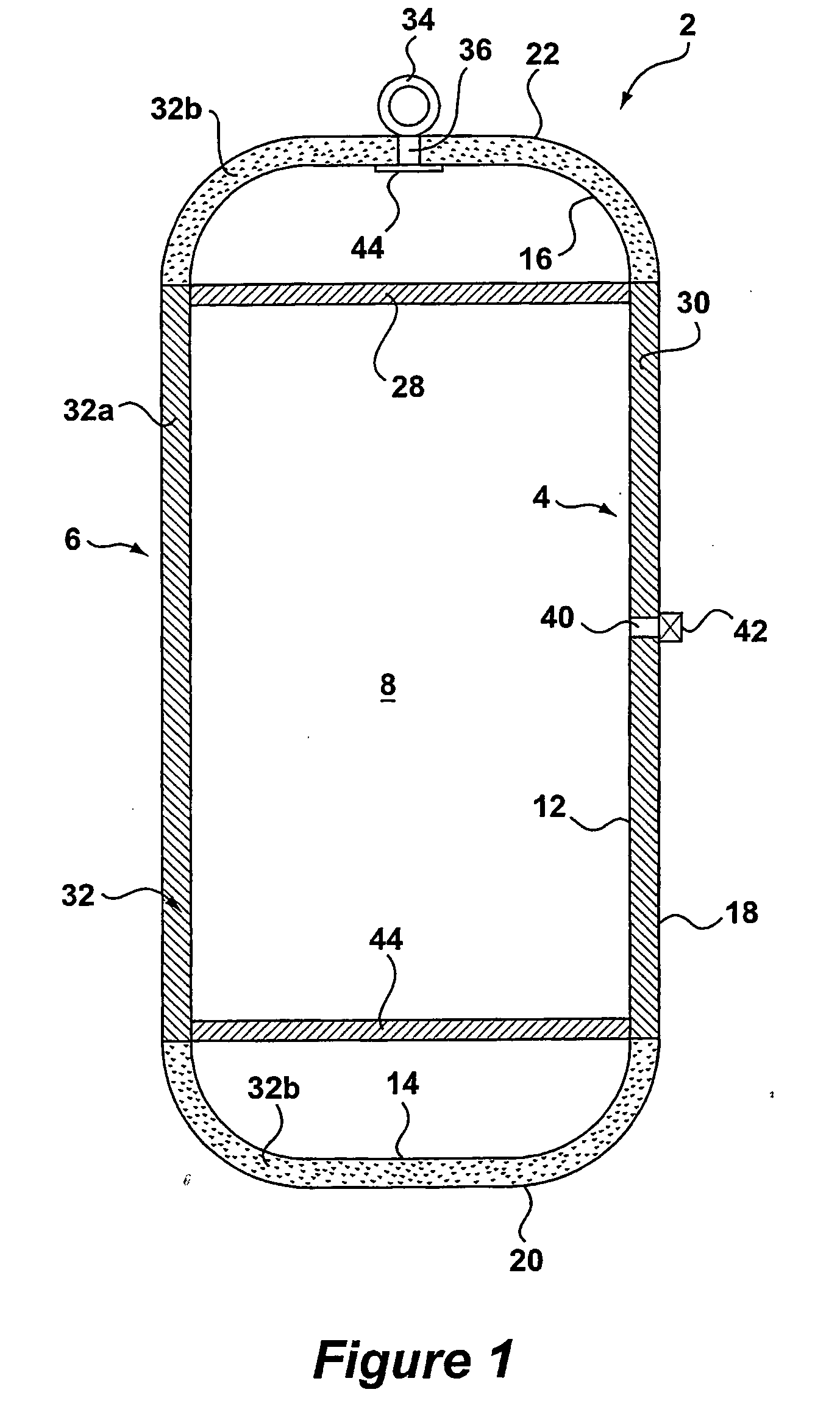
[0181] A series of buoyancy modules were prepared with structures and according to the procedures as described above.

[0182] The modules were assembled with both inner and outer shells prepared from carbon fibres (T700, ex Toray) and epoxy resin (Bakerlite L20). The modules of Examples 1 to 3 were prepared using the carbon fibres and epoxy resin in the form of pre-impregnated fibres in strips (pre-pregs). The remaining modules were prepared using fibres impregnated with resin at the time of fabricating the shells.

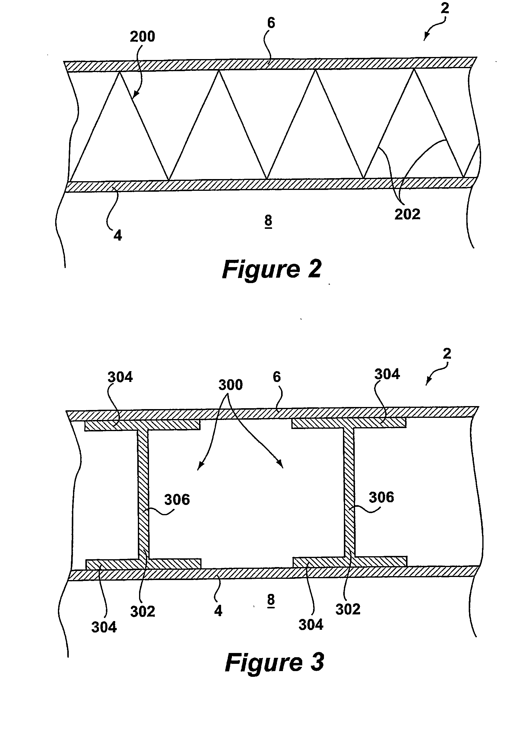
[0183] The modules were prepared having a nominal length of 800 mm. The modules were substantially cylindrical and had flat ends on both the inner and outer housings. The modules of Examples 1 to 4 and 6 to 9 were prepared using a one unit mandrel (nominal length 1000 mm), with one inner shell being formed per run on the mandrel. Example 5 was prepared using a two unit mandrel (nominal length 2000 mm), from which two inner shells could be cut. Generally, a greater similari...


PUM

PropertyMeasurementUnit
Fractionaaaaaaaaaa
Fractionaaaaaaaaaa
Angleaaaaaaaaaa

Abstract

Apparatus for providing an enclosure, for example as a housing or to provide buoyancy, at underwater locations is disclosed comprising an inner shell and an outer shell, with a structural filler disposed between the two. The shells are prepared from fibre-reinforced plastic, with the fibres being oriented to provide resistance to both longitudinal and radial stresses induced in the apparatus by the hydrostatic pressure. The filler may be a structural filler comprising structural members extending between the inner and outer shells and occupying less than 60% of the volume of the cavity between the two shells. Alternatively, the filler may be a substantially void-free structural filler, such as a polyester resin. Methods of fabricating the apparatus are disclosed. In addition, a method of deballasting a buoyancy module is disclosed, in which the ballast, for example water, is withdrawn from the module by means of reduced pressure. Apparatus for deballasting is also disclosed.

Description

TECHNICAL FIELD OF THE INVENTION [0001] The present invention relates to an enclosure apparatus, especially for providing buoyancy to underwater installations, and to a method for constructing the same. The apparatus finds use in a range of underwater applications, in particular for providing buoyancy to underwater structures and installations employed in the exploration and production of oil and gas. The apparatus may also be used at underwater locations to house equipment sensitive to hydrostatic pressure or intolerant of an underwater environment. BACKGROUND OF THE INVENTION [0002] Many underwater operations require the use of devices to provide buoyancy to subsurface structures and installations, as well as to vehicles used underwater. The exploration and production of oil and gas at subsea requires the use of buoyancy in many of its underwater operations. For example, risers extending between a vessel or deck at the surface of the sea or ocean to the wellhead on the sea or ocea...

Claims


Application Information

Patent Timeline
IPC IPC(8): F16L1/00F16L1/12B63B3/13B63B3/20B63B5/24B63C7/08B63C11/42B63G8/22E21B17/01F16L1/24
CPCB63B3/13B63B3/20B63B5/24B63B2231/50B63B2231/52B63C7/08B63C11/42B63G8/22E21B17/012F16L1/24
Inventor DIXON, MARKJACKSON, DAN
Owner COOPER CAMERON CORP
Why Eureka
Try Eureka