
Slide and clip-in corner support

a corner support and clip-in technology, applied in the direction of external fittings, large containers, packaging, etc., can solve the problems of easy collapse of containers, lack of strength and rigidity of collapsible containers, and relatively complicated erecting for use and storag

Inactive Publication Date: 2012-12-18
MCALPINE GILROY CLEMENTS
View PDF15 Cites 4 Cited by
  • Summary
  • Abstract
  • Description
  • Claims
  • Application Information

AI Technical Summary

Benefits of technology

"The present invention provides a new container and reinforcing corner posts that aim to overcome the disadvantages of existing containers. The reinforcing corner posts comprise an external post section and an internal post section that are releasably coupled together and secure the corner of the container. The internal post section and the outer post section each have leaf elements with reinforcing ribs. The engagement means secure the post sections in their engaged position, and the locking means secure the inner post section and the outer post section in their engaged position. The invention also includes a low level platform structure and a hook formation for further locking the disc in position. The outer post sections extend above the upper level of the container to stabilize a plurality of stacked containers."

Problems solved by technology

Known collapsible containers suffer from the disadvantage that they are relatively complicated to erect for use and to collapse for storage and transport purposes, and are consequently not widely accepted by users.
Furthermore, known collapsible containers often lack strength and rigidity, and are consequently easily deformed in use resulting in damage to goods contained therein.
Consequently also such known containers are not suitable for permanent packaging or storage systems.

Method used


Image

  • Slide and clip-in corner support
  • Slide and clip-in corner support
  • Slide and clip-in corner support

Examples


Embodiment Construction

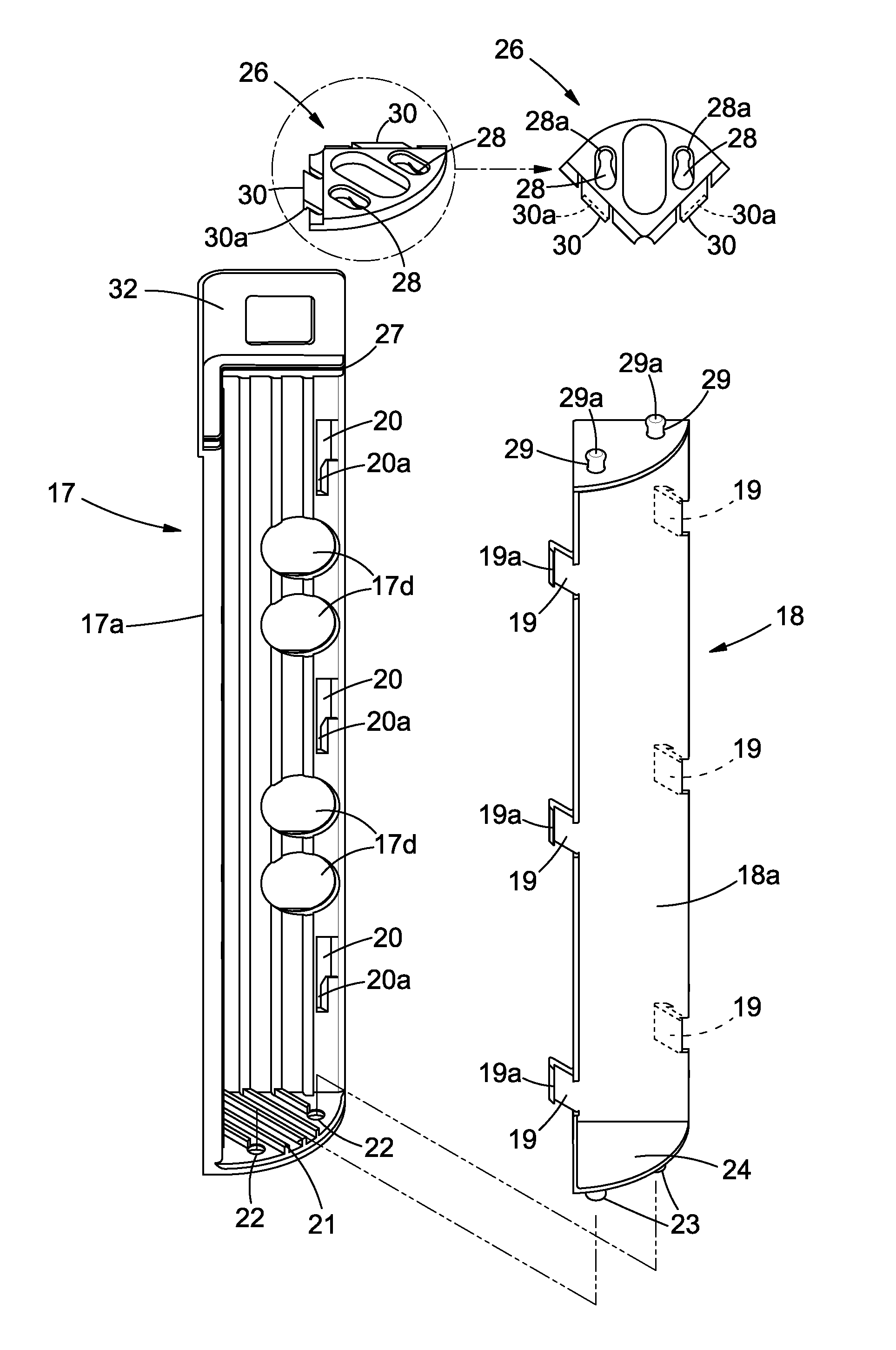
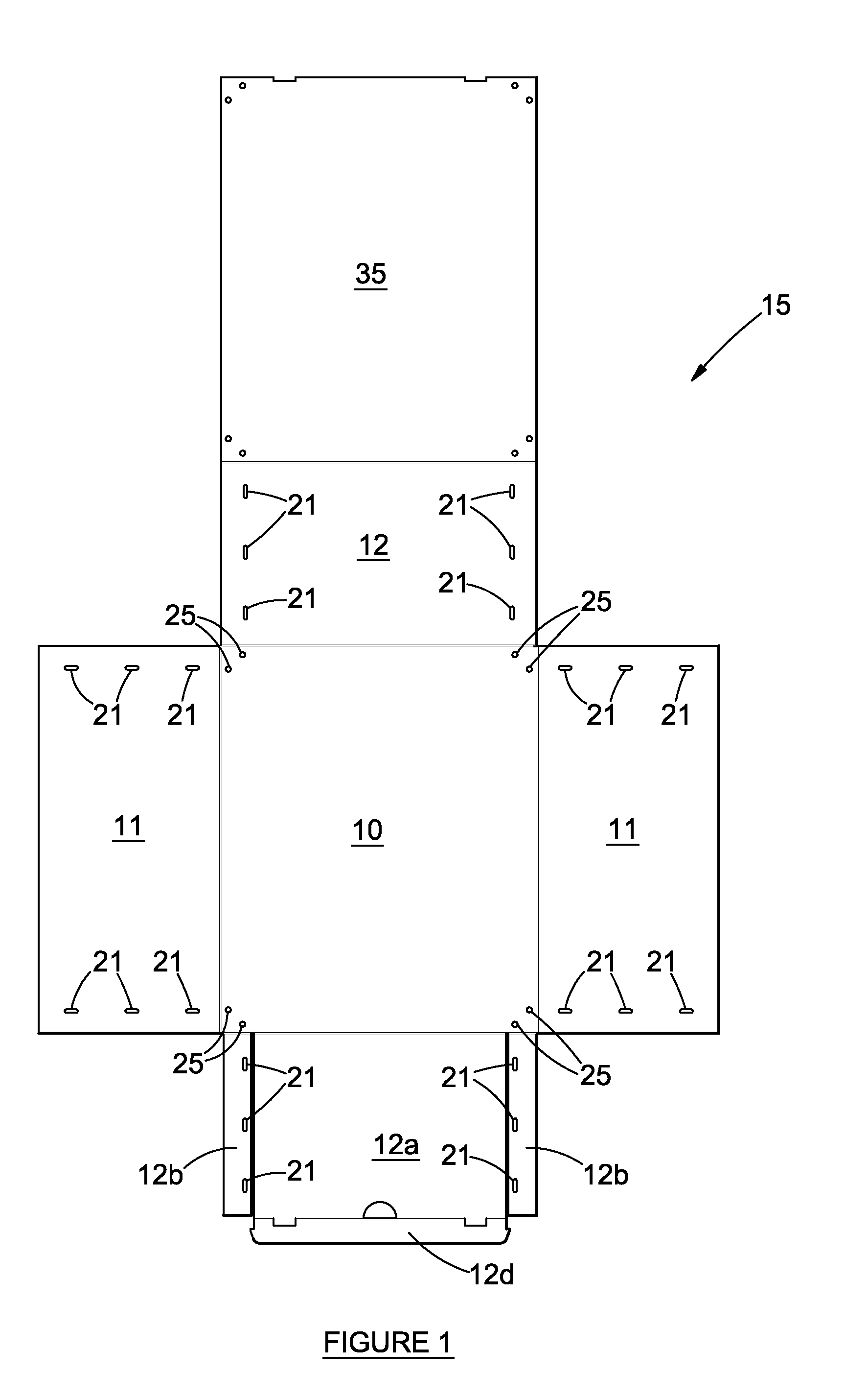
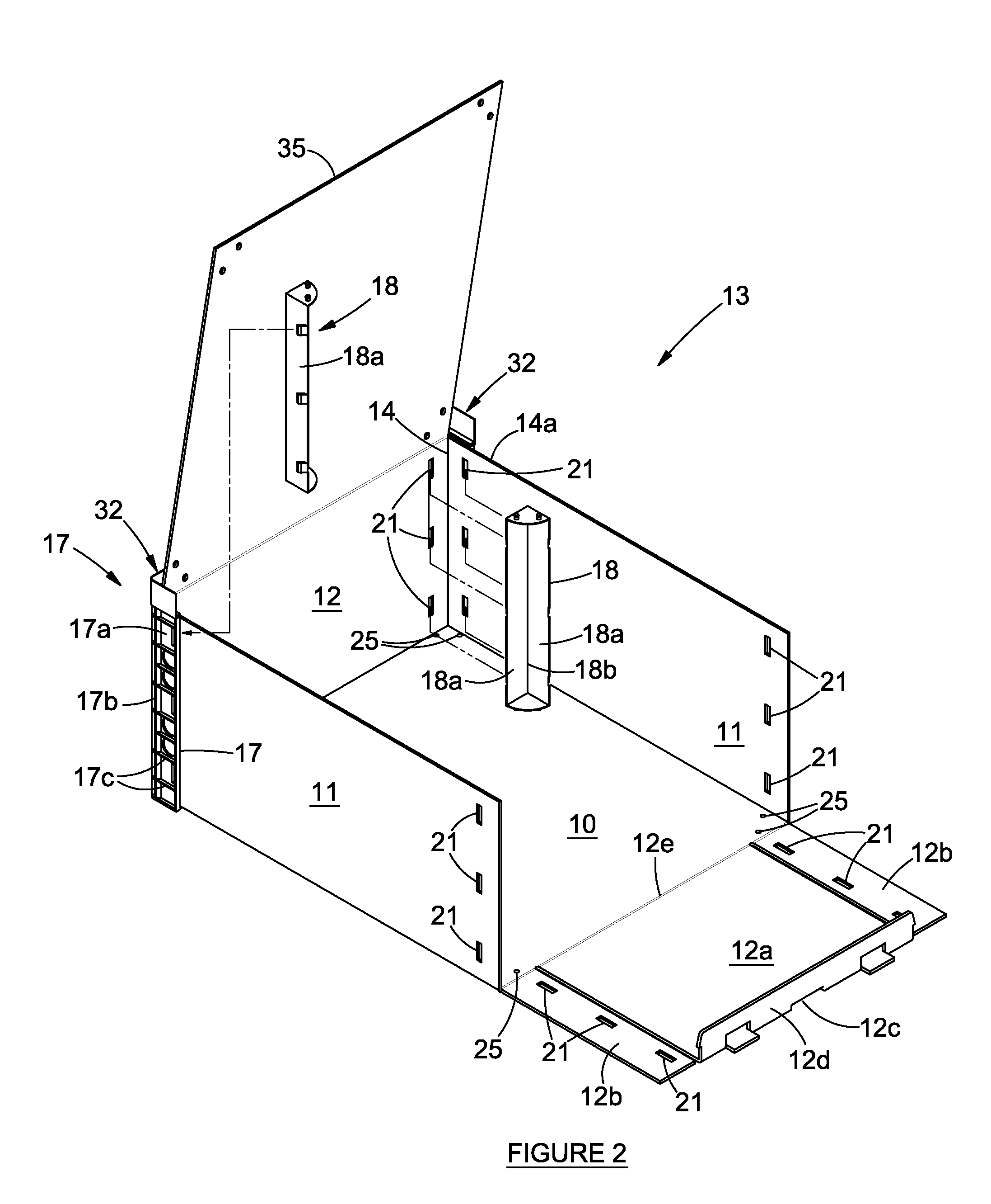
[0027]Referring to the drawings, a collapsible container 13 in accordance with the invention comprises a blank 15 having a base panel 10, opposed side panels 11 and opposed end panels 12 which are adapted to be folded to an upright position relative to the base panel 10 to form opposed side walls 11 and opposed end walls 12 of the container 13. Corners 14 of the container 13 are formed at the intersection between the side walls 11 and end walls 12 as illustrated (FIGS. 2, 3).

[0028]FIGS. 2 to 4 illustrate the various steps which are taken to fold the blank in FIG. 1 into an erected container having reinforcing corner posts 17, as shown in FIG. 4. The container in FIGS. 2 to 4 includes one end panel 12a which is hinged along a fold-line 12e to enable the panel 12a to fold to an open position. The panel 12a has an end tab 12d and a manipulating aperture 12c. Side tabs 12b are hinged at right angles to the floor panel 10 and form corners 14 together with the side panels 11 (FIG. 3). Thi...


PUM


Abstract

The invention provides a reinforcing corner post suitable for use with a container comprising a foldable blank having a base panel and a pair of opposed side wall panels, and a pair of opposed end wall panels, the side wall panels and end wall panels being foldable into upright positions relative to the base panel to define opposed side walls and end walls with corners being formed at the junctions of the side walls and end walls, the reinforcing corner post being provided at all or selected corners of the container, wherein the corner post comprises an external post section which embraces the corner, and an internal post section which nests within the corner, and engaging means for releasably coupling the external post section and internal post section to one another by longitudinal displacement of the external post section and internal post section relative to one another to an engaged position, and locking means for securing the inner post section and the outer post section in the engaged position.

Description

CROSS-REFERENCE TO RELATED APPLICATIONS[0001]The present application is a 35 U.S.C. §§371 national phase conversion of PCT / IB2006 / 054022, filed Oct. 31, 2006, which claims priority of South African Patent Application No. 2005 / 08904, filed Nov. 3, 2005, the disclosure of which has been incorporated herein by reference. The PCT International Application was published in the English language.FIELD OF THE INVENTION[0002]THIS invention relates to a container and reinforcing corner posts for use with the container in its erected configuration.BACKGROUND TO THE INVENTION[0003]Various collapsible containers are available. These are particularly useful for produce such as fruit and vegetables, but are not confined to the conveyance and storage of such produce.[0004]Known collapsible containers suffer from the disadvantage that they are relatively complicated to erect for use and to collapse for storage and transport purposes, and are consequently not widely accepted by users. Furthermore, kn...

Claims


Application Information

Patent Timeline
Patent Type & Authority Patents(United States)
IPC IPC(8): B65D6/34
CPCB65D5/006B65D7/44B65D9/36B65D5/42
Inventor MCALPINEALGATE, DANIEL ROBERT
Owner MCALPINE GILROY CLEMENTS
Learn More