Magnetic head for perpendicular magnetic recording having a main pole and a shield and specifically structured and located coil elements and magnetic coupling layers

a perpendicular magnetic and recording technology, applied in the field of magnetic head for perpendicular magnetic recording, can solve the problems of unfavorable no scheme has been devised to prevent undesirable protrusion of part of the medium facing surface, and the length of the magnetic path, so as to reduce the magnetic path length of the return path section and prevent undesirable protrusion of par

Active Publication Date: 2013-01-01
HEADWAY TECH INC +1
View PDF3 Cites 16 Cited by
  • Summary
  • Abstract
  • Description
  • Claims
  • Application Information

AI Technical Summary

Benefits of technology

[0014]It is an object of the present invention to provide a magnetic head for perpendicular magnetic recording that allows preventing undesirable protrusion of part of the medium facing surface from being caused by a coil and a magnetic layer that forms a return path section, and allows reducing the magnetic path length of the return path section.
[0022]In the first or second magnetic head of the present invention, the end face of the second coupling layer that faces toward the medium facing surface is located away from the medium facing surface. This serves to prevent undesirable protrusion of part of the medium facing surface from being caused by the coil and a magnetic layer that forms a return path section. In the present invention, a single first coil element is disposed with the first coupling layer interposed between the medium facing surface and the first coil element. A plurality of second coil elements are disposed with the second coupling layer interposed between the medium facing surface and the second coil elements, and with the first coil element interposed between the main pole and the second coil elements. The second coil elements are aligned in the direction perpendicular to the medium facing surface. Such a configuration allows the first coil element to be disposed in a narrow space between the main pole and the plurality of second coil elements, while allowing the first coupling layer to be reduced in length in the direction perpendicular to the top surface of the substrate and thereby allowing the end face of the first coupling layer located in the medium facing surface to be reduced in area. Thus, according to the present invention, the space defined by the main pole, the gap part, the write shield, the first coupling layer, the second coupling layer and the yoke part can be efficiently used to dispose the coil. This makes it possible to reduce the magnetic path length of the return path section. Consequently, according to the present invention, it is possible to prevent undesirable protrusion of part of the medium facing surface from being caused by the coil and a magnetic layer that forms a return path section, and also reduce the magnetic path length of the return path section.

Problems solved by technology

In such a structure, heat generated by the coil may cause the magnetic layer to expand, and this may result in undesirable protrusion of part of the medium facing surface.
However, no scheme has been devised to prevent undesirable protrusion of part of the medium facing surface from being caused by a coil and a magnetic layer that forms a return path section, and to reduce the magnetic path length of the return path section.

Method used


Image

  • Magnetic head for perpendicular magnetic recording having a main pole and a shield and specifically structured and located coil elements and magnetic coupling layers
  • Magnetic head for perpendicular magnetic recording having a main pole and a shield and specifically structured and located coil elements and magnetic coupling layers
  • Magnetic head for perpendicular magnetic recording having a main pole and a shield and specifically structured and located coil elements and magnetic coupling layers

Examples


Embodiment Construction

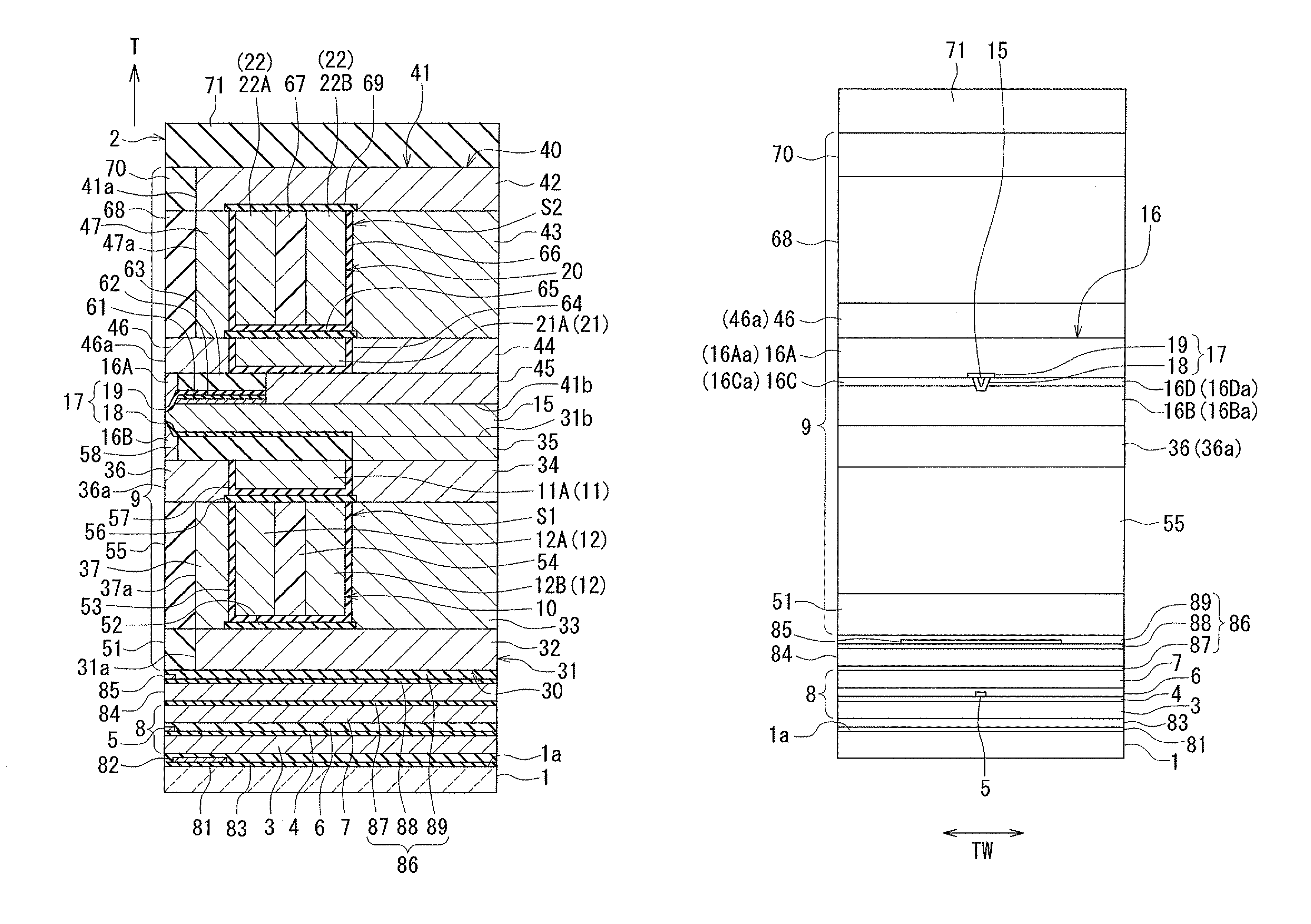
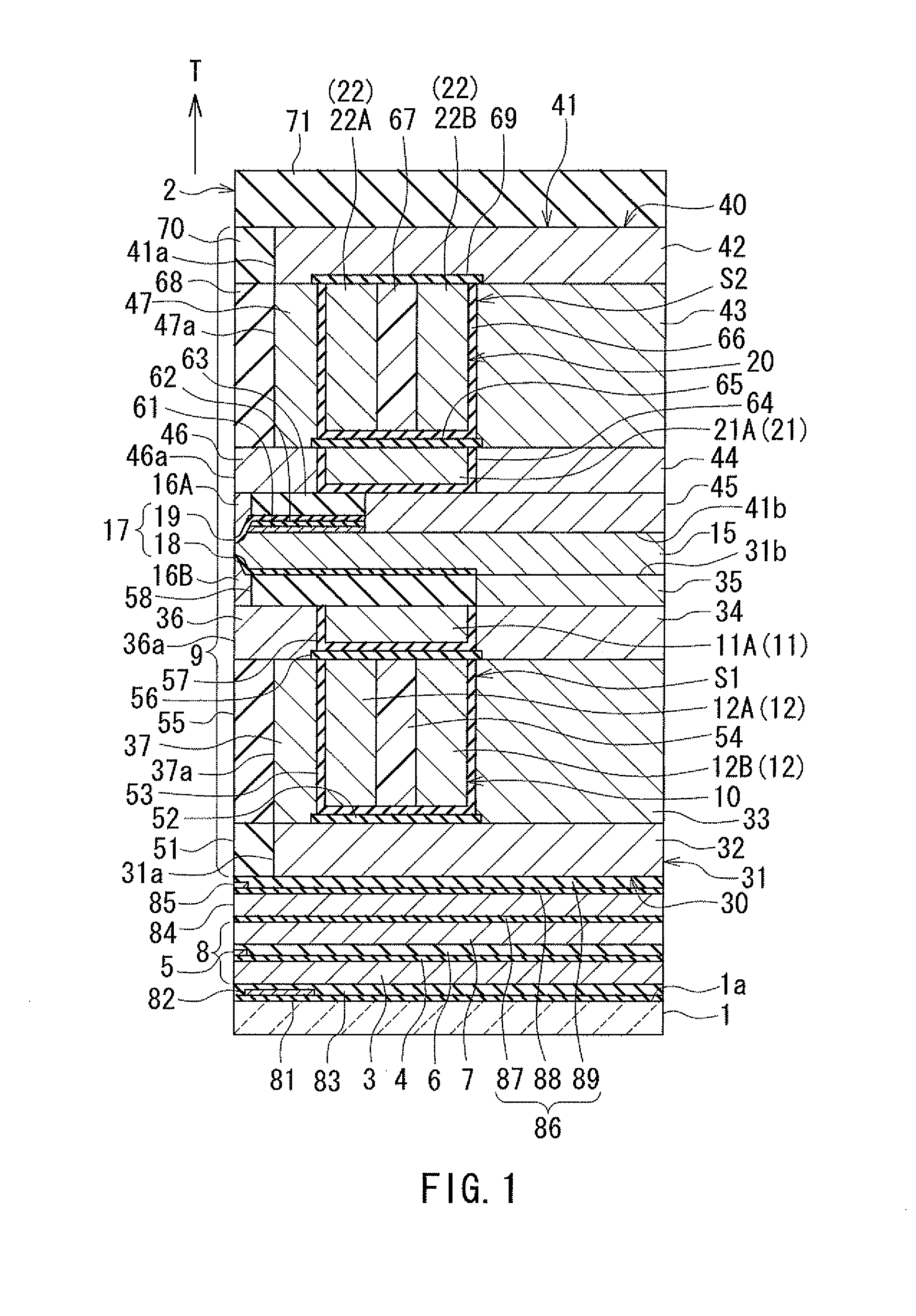
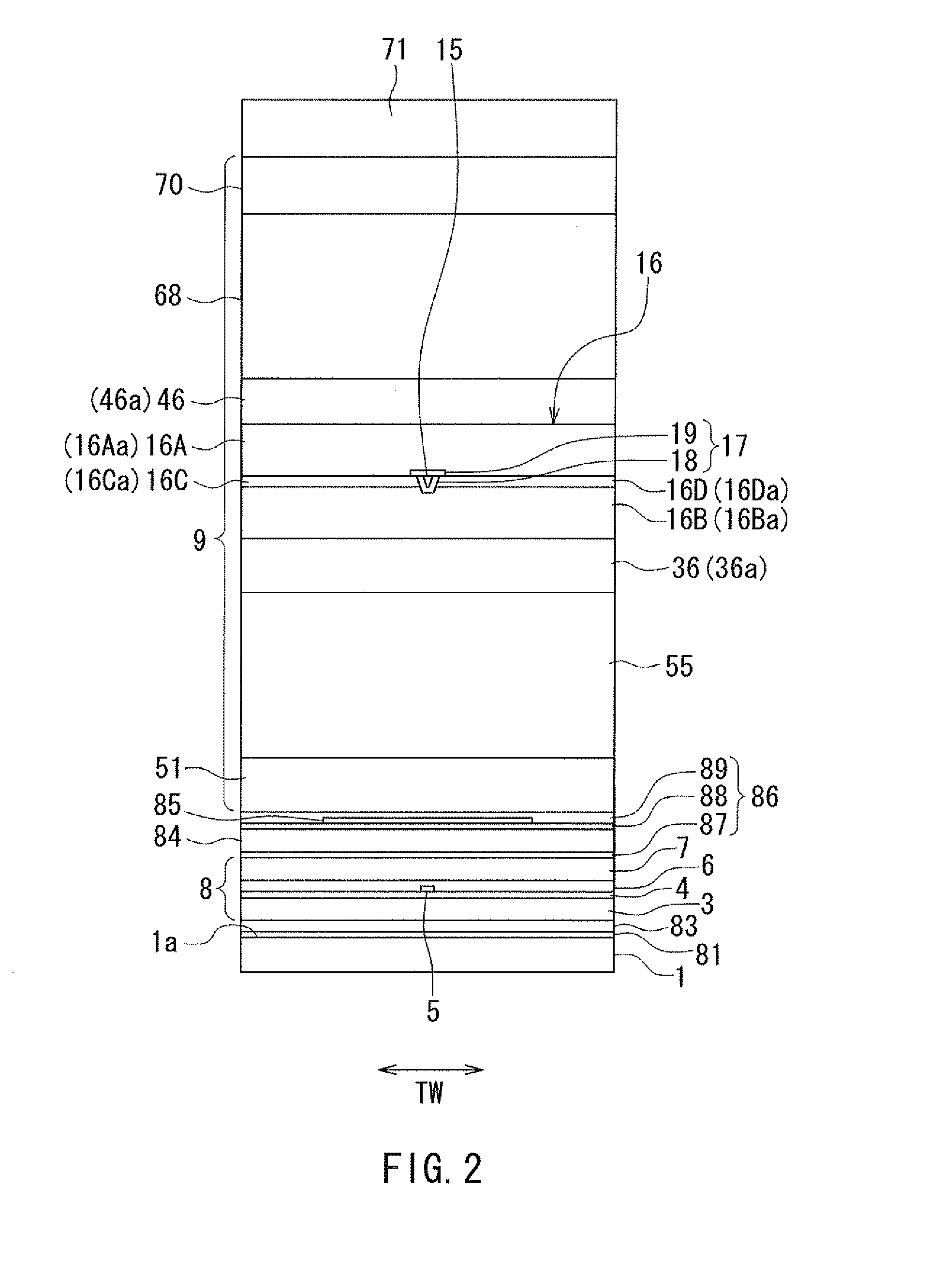
[0031]An embodiment of the present invention will now be described in detail with reference to the drawings. First, reference is made to FIG. 1 to FIG. 7 to describe the configuration of a magnetic head according to the embodiment of the invention. FIG. 1 is a cross-sectional view of the magnetic head according to the embodiment. Note that FIG. 1 shows a cross section perpendicular to the medium facing surface and the top surface of the substrate. The arrow with the symbol T in FIG. 1 indicates the direction of travel of the recording medium. FIG. 2 is a front view showing the medium facing surface of the magnetic head according to the embodiment. FIG. 3 is a plan view showing a second layer of a first portion of a coil of the magnetic head according to the embodiment. FIG. 4 is a plan view showing a first layer of the first portion of the coil of the magnetic head according to the embodiment. FIG. 5 is a plan view showing a first layer of a second portion of the coil of the magneti...


PUM

PropertyMeasurementUnit
thicknessaaaaaaaaaa
thicknessaaaaaaaaaa
heightaaaaaaaaaa

Abstract

A magnetic head includes a coil, a main pole, a gap part, a write shield, and a return path section. The return path section includes a yoke part with a first coupling layer connected to the write shield and a second coupling layer magnetically coupling the first coupling layer to the yoke part. The second coupling layer has an end face facing toward a medium facing surface and located away from the medium facing surface. The coil includes i) a first coil element disposed with the first coupling layer interposed between the medium facing surface and the first coil element and ii) a plurality of second coil elements aligned perpendicularly to the medium facing surface and disposed with the second coupling layer interposed between the medium facing surface and the second coil elements. The first coil element being interposed between the main pole and the second coil elements.

Description

BACKGROUND OF THE INVENTION[0001]1. Field of the Invention[0002]The present invention relates to a magnetic head for perpendicular magnetic recording that is used for writing data on a recording medium by means of a perpendicular magnetic recording system, and more specifically, to a magnetic head for perpendicular magnetic recording that includes a main pole and a shield.[0003]2. Description of Related Art[0004]The recording systems of magnetic read / write apparatuses include a longitudinal magnetic recording system wherein signals are magnetized in a direction along the plane of the recording medium (the longitudinal direction) and a perpendicular magnetic recording system wherein signals are magnetized in a direction perpendicular to the plane of the recording medium. It is known that the perpendicular magnetic recording system is harder to be affected by thermal fluctuation of the recording medium and capable of providing higher linear recording density, compared with the longitu...

Claims


Application Information

Patent Timeline
Patent Type & Authority Patents(United States)
IPC IPC(8): G11B5/17G11B5/127
CPCG11B5/1278G11B5/3123G11B5/315
Inventor SASAKI, YOSHITAKAITO, HIROYUKISATO, KAZUKIIIJIMA, ATSUSHI
Owner HEADWAY TECH INC
Why Eureka
Try Eureka