Cannulated flexible drive shaft

a flexible drive shaft and cannula technology, applied in the field of tools used, can solve the problems that the conventional straight drive shaft is not well suited for such procedures

Active Publication Date: 2013-02-05
LENKBAR
View PDF25 Cites 1185 Cited by
  • Summary
  • Abstract
  • Description
  • Claims
  • Application Information

AI Technical Summary

Benefits of technology

[0007]A further object of the present invention is to provide a flexible drive shaft that is strong enough to withstand the torque being placed on it while in use.
[0008]The present invention fulfills the above and other objects by providing a flexible cannulated drive shaft having a plurality of interlocking sections having an angled dovetail design cut into the drive shaft. Each interlocking section has a proximal end, a distal end and a dovetail design comprising substantially triangular-shaped pins and substantially triangular-shaped sockets that alternate around the circumference of the proximal end and / or distal end of each interlocking section. The pins of one interlocking section moveably engage the sockets of a second interlocking section and vice versa. The substantially triangular-shaped pins and substantially triangular-shaped sockets secure the interlocking sections together while allowing the drive shaft to be flexible. An additional benefit of the interlocking sections is that the distance between each section may be cut larger or smaller to achieve a more or less flexible drive shaft. Furthermore, the substantially triangular-shaped pins and substantially triangular-shaped sockets stay locked together whether the drive shaft is being rotated clockwise or counterclockwise. The drive shaft may be used as a manual tool, such as a screw driver, or attached to a rotational tool, such as a drill. A guide allows a user to control the placement and depth of the distal end of the drive shaft during operations.

Problems solved by technology

The limitations on maneuverability imposed by arthroscopic surgery mean that conventional straight drive shafts are not well suited for such procedures.

Method used


Image

  • Cannulated flexible drive shaft
  • Cannulated flexible drive shaft
  • Cannulated flexible drive shaft

Examples


Embodiment Construction

[0025]For purposes of describing the preferred embodiment, the terminology used in reference to the numbered components in the drawings is as follows:

[0026]

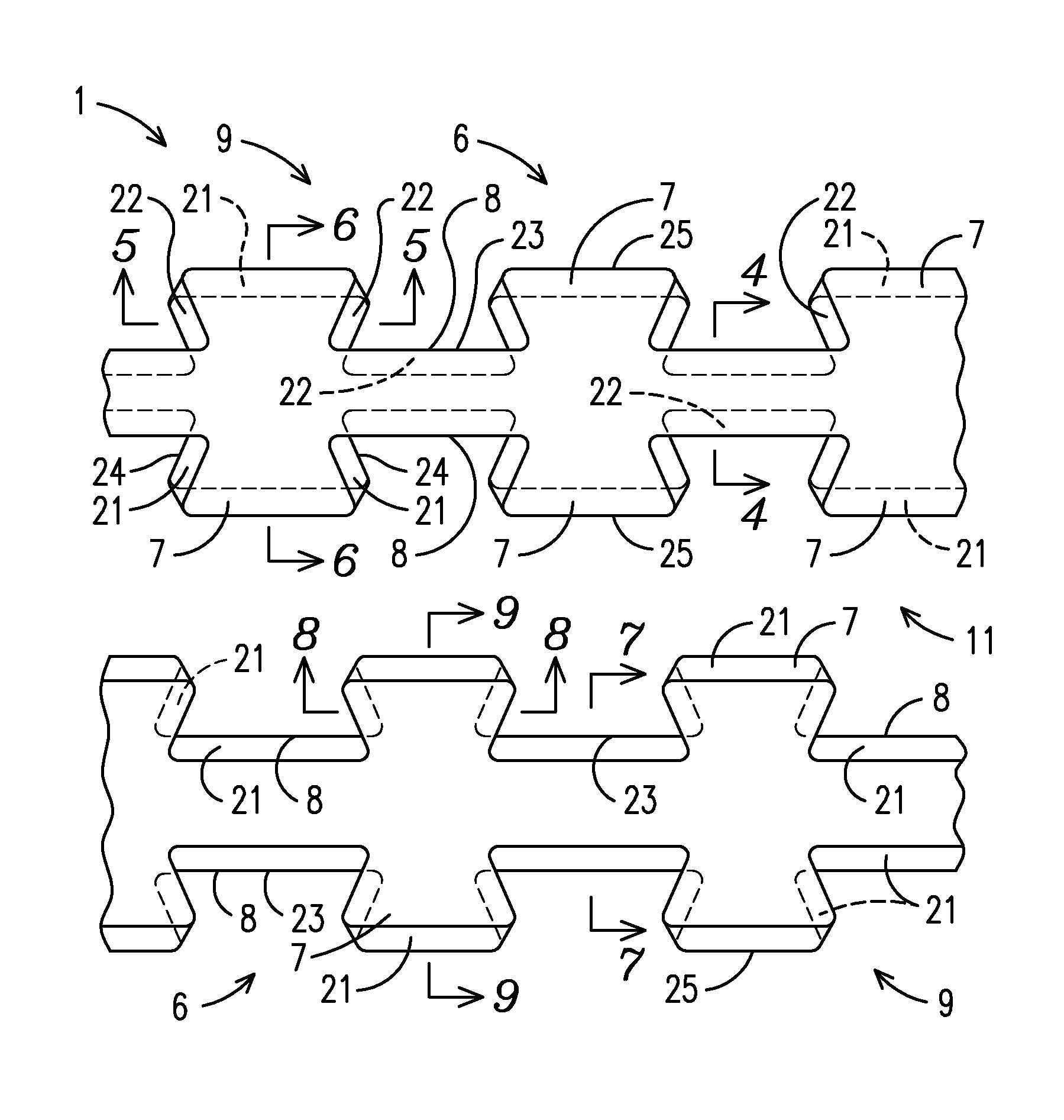
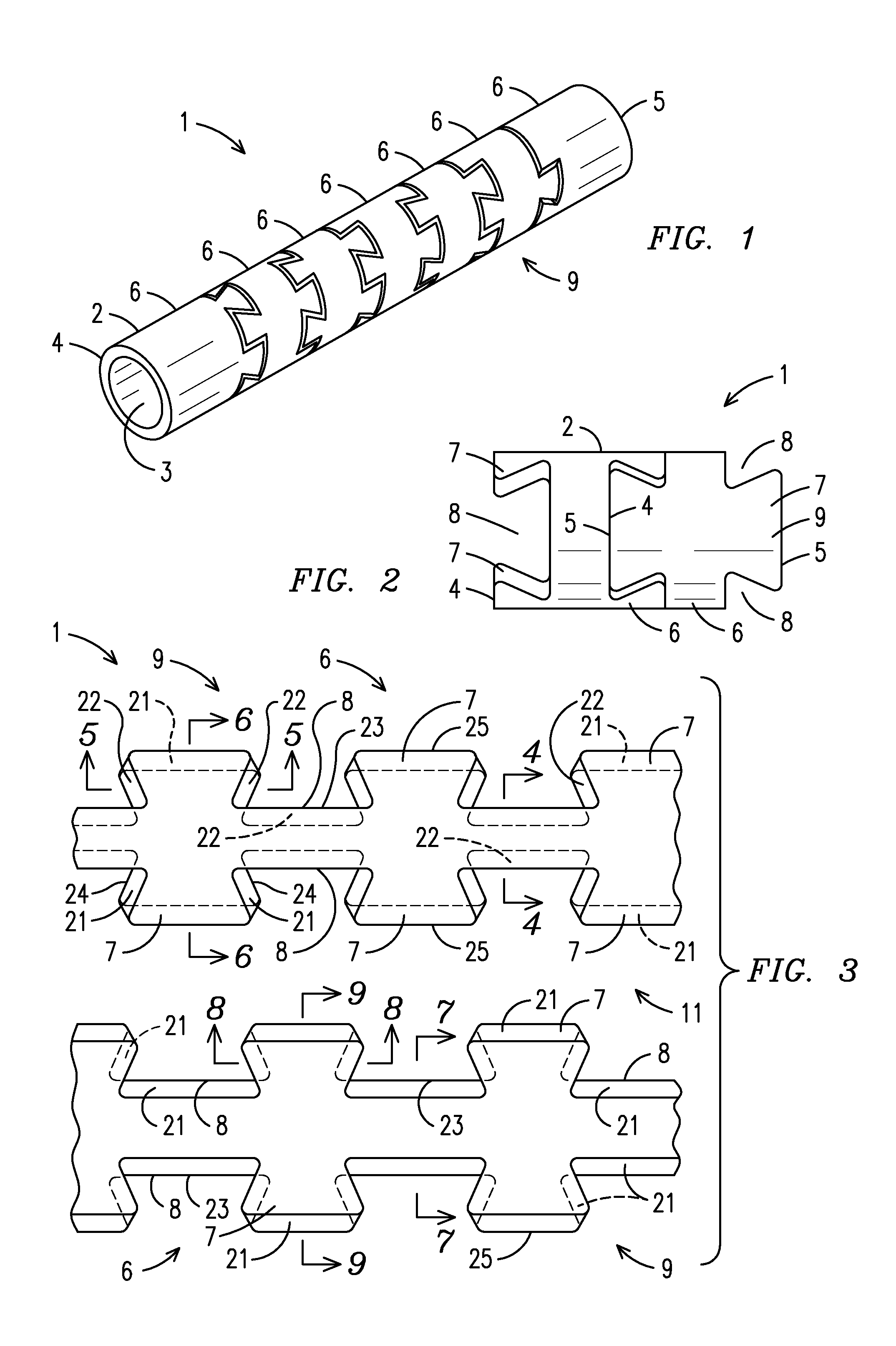
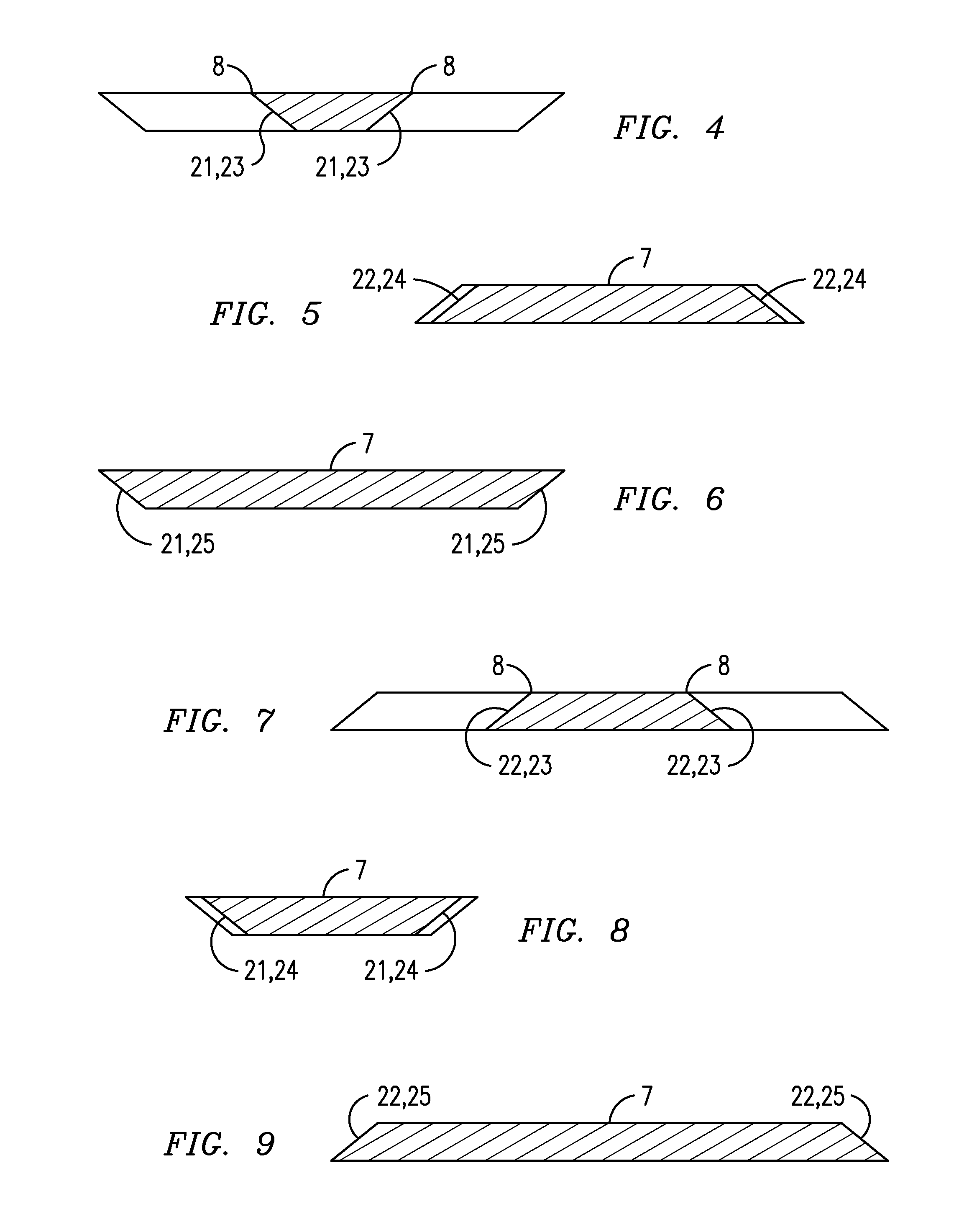
 1. drive shaft 2. outer surface 3. inner surface 4. proximal end 5. distal end 6. interlocking section 7. pin 8. socket 9. template10. tubular shaft11. cut12. edge13. screw driver14. suture anchor15. handle16. hollow portion17. external guide18. stop19. head20. suture21. inward angled surface22. outward angled surface23. inner portion of socket24. side portion of pin25. outer portion of pin26. internal guide27. handle28. protective sheath

[0027]With reference to FIGS. 1 and 2, a side perspective view of a flexible cannulated drive shaft 1 of the present invention and a side view of interlocking sections 6 of the present invention, respectively, are shown. The drive shaft 1 is preferably tubular and comprises an outer surface 2, an inner surface 3, a proximal end 4 and a distal end 5. A plurality of interlocking sections 6 are loc...


PUM


Abstract

A flexible cannulated drive shaft having a plurality of interlocking sections having multi-angled dovetails cut into the drive shaft. Each dovetail design is made up of substantially triangular-shaped pins and substantially triangular-shaped sockets that alternate around the circumference of each interlocking section. The pins of one interlocking section moveably engage the sockets of a second interlocking section and vice versa. Furthermore, the substantially triangular-shaped pins and substantially triangular-shaped sockets stay locked together whether the drive shaft is being rotated clockwise or counterclockwise. Angled surfaces add greater stability to the drive shaft and prevent the interlocking sections from coming apart.

Description

CROSS REFERENCE TO RELATED APPLICATION[0001]This application claims the benefit of U.S. Provisional Patent Application No. 61 / 357,651, filed Jun. 23, 2010. The patent application identified above is incorporated herein by reference in its entirety to provide continuity of disclosure.BACKGROUND OF THE INVENTION[0002]This invention relates to tools used for performing surgeries, such as arthroscopic or orthopedic procedures, more particularly, a cannulated flexible drive shaft having a plurality of interlocking sections, preferably locked together by multi-angled dovetails, along the shaft that allow a distal end to be flexible while withstanding the torque from being rotated clockwise or counterclockwise thereby preventing the dovetails from separating and failing.[0003]The limitations on maneuverability imposed by arthroscopic surgery mean that conventional straight drive shafts are not well suited for such procedures. Therefore, various arthroscopic surgical procedures utilize flex...

Claims


Application Information

Patent Timeline
Patent Type & Authority Patents(United States)
IPC IPC(8): F16D3/18
CPCA61B17/1631
Inventor PAPENFUSS, ERIK H.PAPENFUSS, HANS B.
Owner LENKBAR
Why Eureka
Try Eureka