Image capturing lens assembly

a technology of image capturing and lens assembly, which is applied in the field of image capturing lens assembly, can solve the problems of limited ability to correct aberration and chromatic aberration, prone inability to produce blurry images, so as to achieve excellent image quality, reduce power consumption, and improve image quality

Active Publication Date: 2013-02-05
LARGAN PRECISION
View PDF3 Cites 37 Cited by
  • Summary
  • Abstract
  • Description
  • Claims
  • Application Information

AI Technical Summary

Benefits of technology

[0010]By such arrangement and focusing adjustment method, good image quality is achieved and less power is consumed.
[0011]The image capturing lens assembly of the present invention has the ability to perform focusing by movements among lens groups, wherein focusing by adjusting the movable first lens group results in excellent image quality where the imaged object is at an extremely close site or an extremely far site.
[0012]In the aforementioned image capturing lens assembly, the first lens element has a positive refractive power, which thereby can reduce the total track length favorably. The second lens element has a negative refractive power, and thereby the aberration of the lens assembly can be effectively corrected and the image quality thereof can be favorably improved. The fourth lens element has a positive refractive power, and thereby the total track length of the lens assembly can be effectively reduced and the sensitivity thereof can be also reduced. The fifth lens element has a negative refractive power, and thereby the high order aberration of the lens assembly can be effectively corrected.
[0013]In the aforementioned image capturing lens assembly, the second lens group of the present invention, in comparison with the one in a conventional image lens system focusing by the movement of the lens elements thereof (such as the one disclosed in U.S. Pat. No. 7,777,972), contains an additional lens element with a refractive power, which is critical to the image quality thereof. If the aforementioned lens element has a positive refractive power, it can be served as a correcting lens element for better correction of the aberration of the lens assembly; whereas, if the aforementioned lens element has a negative refractive power, the negative refractive power can provide good effect on correcting the chromatic aberration of the lens assembly.
[0014]In the aforementioned image capturing lens assembly, when the first lens element has a convex object-side surface, the positive refractive power of the lens elements can be strengthened and thereby the total track length of the lens assembly can be reduced even more. When the second lens element has a concave image lens element, the aberration of the lens assembly can be corrected favorably. When the fourth lens element has a concave object-side surface and a convex image-side surface, it is favorable for the correction of the astigmatism of the lens assembly. When the fifth lens element has a concave object-side surface, the high order aberration of the lens assembly can be favorably corrected. When the fifth lens element has a concave image-side surface, the principle point can be positioned away from the image plane and thereby reducing the total track length of the lens assembly.

Problems solved by technology

For a specific object distance, since the photographing lens assembly has a limited depth of field, it is apt to produce blurry images.
As the system with five lens elements disclosed in U.S. Pat. No. 7,864,454, which is designed to perform focusing by the movement of the whole lens system, has a limited depth of field while focusing at an extremely close site and thereby obtains blurry peripheral images so that causing deficiency in image quality.
However, the second lens group thereof is configured with only three lens elements and thereby the ability to correct aberration and chromatic aberration is limited.
However, such a photographing lens assembly requires higher power consumption because the driving motor is configured to drive the entire photographing lens assembly.
Moreover, the photographing lens assembly has a relatively long total track length.

Method used


Image

  • Image capturing lens assembly
  • Image capturing lens assembly
  • Image capturing lens assembly

Examples


embodiment 1

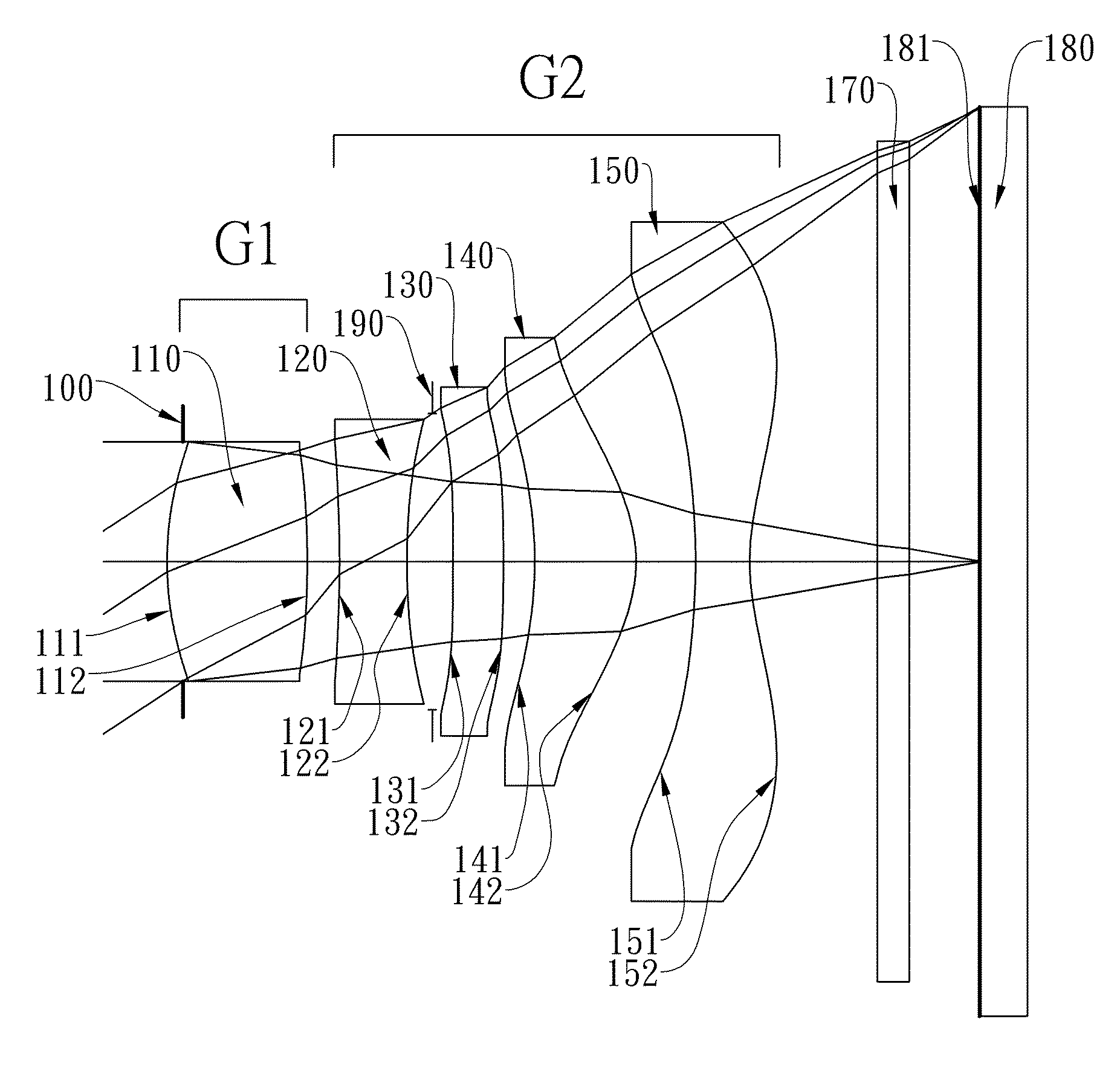
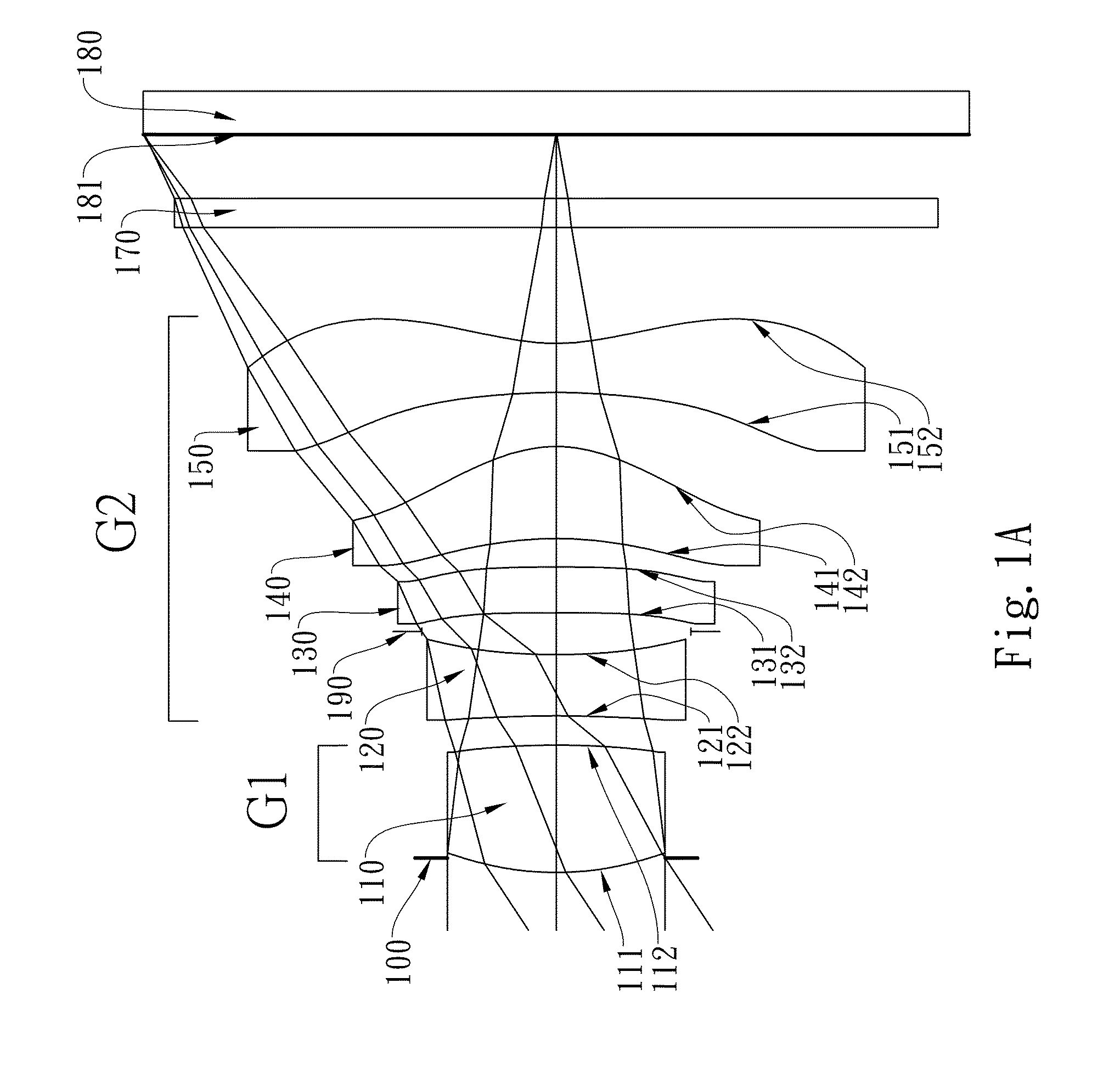
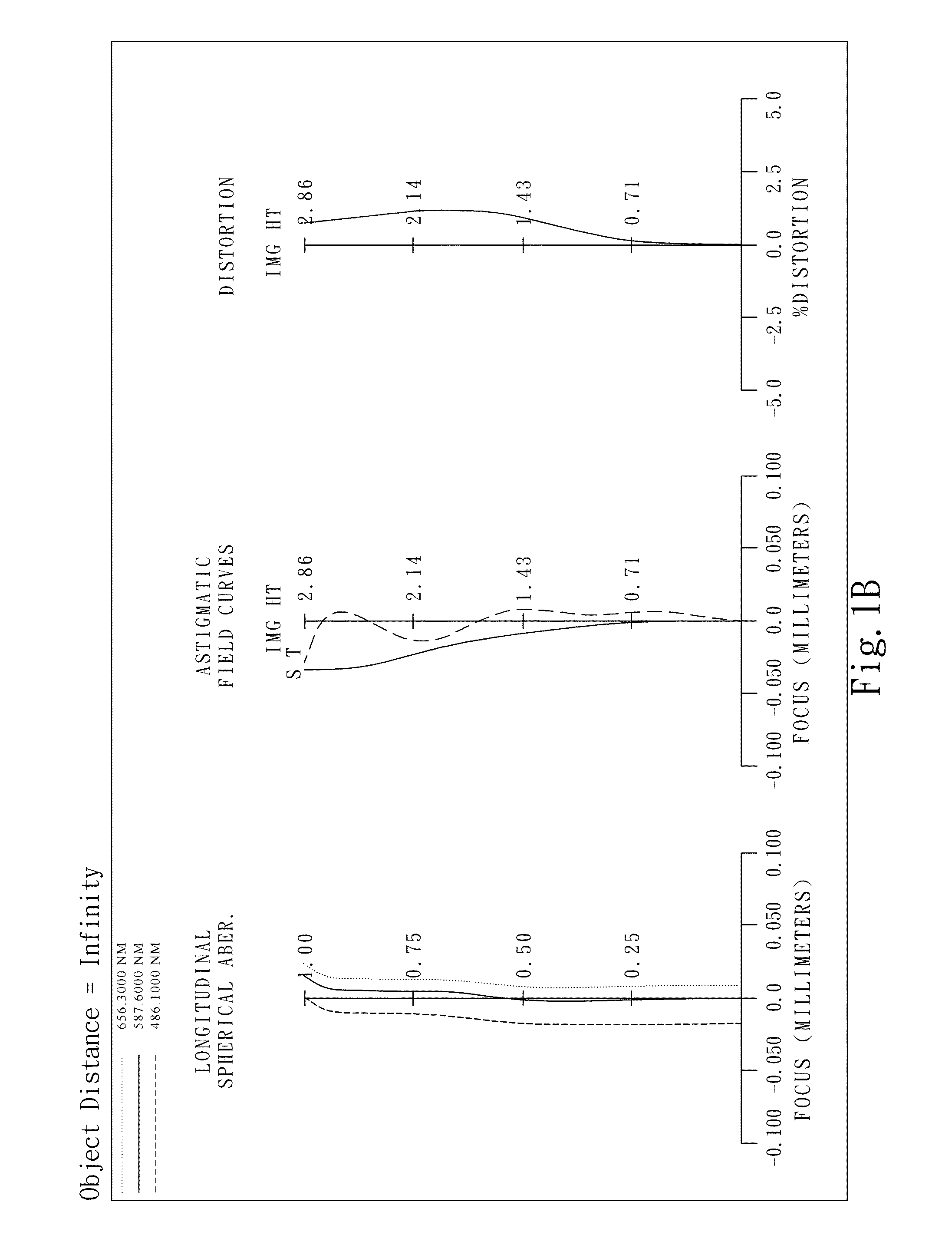
[0072]FIG. 1A shows an image capturing lens assembly in accordance with the first embodiment of the present invention; meanwhile, FIG. 1B shows the aberration curves of the first embodiment as a distance between the lens assembly and an imaged object is infinite, and FIG. 1C shows the aberration curves as a distance between the lens assembly and the imaged object is 100 mm. The image capturing lens assembly of the first embodiment of the present invention mainly comprises five lens elements, in order from an object side to an image side:

[0073]a first lens group G1, comprising a first lens element 110 made of plastic with a positive refractive power having a convex object-side surface 111 and a convex image-side surface 112, the object-side and image-side surfaces 111 and 112 thereof being aspheric; and

[0074]a second lens group G2, comprising, in order from an object side to an image side:

[0075]a second lens element 120 made of plastic with a negative refractive power having a concav...

embodiment 2

[0105]FIG. 2A shows an image capturing lens assembly in accordance with the second embodiment of the present invention; meanwhile, FIG. 2B shows the aberration curves of the second embodiment as a distance between the lens assembly and an imaged object is infinite, and FIG. 2C shows the aberration curves as a distance between the lens assembly and the imaged object is 100 mm. The image capturing lens assembly of the second embodiment of the present invention mainly comprises five lens elements, in order from an object side to an image side:

[0106]a first lens group G1, comprising a first lens element 210 made of plastic with a positive refractive power having a convex object-side surface 211 and a concave image-side surface 212, the object-side and image-side surfaces 211 and 212 thereof being aspheric; and

[0107]a second lens group G2, comprising, in order from an object side to an image side:

[0108]a second lens element 220 made of plastic with a negative refractive power having a co...

embodiment 3

[0119]FIG. 3A shows an image capturing lens assembly in accordance with the third embodiment of the present invention; meanwhile, FIG. 3B shows the aberration curves of the third embodiment as a distance between the lens assembly and an imaged object is infinite, and FIG. 3C shows the aberration curves as a distance between the lens assembly and the imaged object is 100 mm. The image capturing lens assembly of the third embodiment of the present invention mainly comprises five lens elements, in order from an object side to an image side:

[0120]a first lens group G1, comprising a first lens element 310 made of plastic with a positive refractive power having a convex object-side surface 311 and a convex image-side surface 312, the object-side and image-side surfaces 311 and 312 thereof being aspheric; and

[0121]a second lens group G2, comprising, in order from an object side to an image side:

[0122]a second lens element 320 made of plastic with a negative refractive power having a convex...


PUM


Abstract

This invention provides an image capturing lens assembly in order from an object side to an image side comprising: a first lens group has only one first lens element with a positive refractive power, and a second lens group in order from the object side to the image side comprising: a second lens element with a negative refractive power, a third lens element, a fourth lens element and a fifth lens element; while a distance between an imaged object and the image capturing lens assembly changes from far to near, focusing is performed by moving the first lens group along the optical axis and a distance between the first lens group and an image plane changes from near to far. By such arrangement and focusing adjustment method, good image quality is achieved and less power is consumed.

Description

CROSS-REFERENCE TO RELATED APPLICATIONS[0001]This non-provisional application claims priority under 35 U.S.C. §119(a) on Patent Application No. 100105726 filed in Taiwan, R.O.C. on Feb. 22, 2011, the entire contents of which are hereby incorporated by reference.BACKGROUND OF THE INVENTION[0002]1. Field of the Invention[0003]The present invention relates to an image capturing lens assembly, and more particularly, to a compact image capturing lens assembly used in electronic products.[0004]2. Description of the Prior Art[0005]In recent years, with the popularity of camera equipped in a mobile phone, the demand for compact photographing lens assemblies is increasing, and the sensor of a general photographing camera is none other than CCD (Charge Coupled Device) or CMOS device (Complementary Metal Oxide Semiconductor device). Furthermore, as advanced semiconductor manufacturing technology has reduced the pixel size of sensors and compact photographing lens assemblies have gradually evol...

Claims


Application Information

Patent Timeline
Patent Type & Authority Patents(United States)
IPC IPC(8): G02B9/00
CPCG02B9/10G02B13/0045
Inventor TANG, HSIANG CHIHSIEH, DUNG YITSAI, TSUNG HAN
Owner LARGAN PRECISION
Why Eureka
Try Eureka