Infrared and visible imaging of documents

a visible imaging and infrared technology, applied in the field of infrared and visible imaging of documents, can solve the problems of unidentifiable micr characters, unnecessary separate power connections,

Active Publication Date: 2013-02-19
AMBIR TECH
View PDF17 Cites 8 Cited by
  • Summary
  • Abstract
  • Description
  • Claims
  • Application Information

AI Technical Summary

Problems solved by technology

It draws all the electricity it needs from a standard USB 2.0 port, making a separate power connection unnecessary.
Such hand-written marks could make the MICR characters unidentifiable unless a way is found to separate the hand-written marks from the printed MICR characters.

Method used


Image

  • Infrared and visible imaging of documents
  • Infrared and visible imaging of documents
  • Infrared and visible imaging of documents

Examples


Embodiment Construction

[0030]In the following detailed description, numerous specific details are set forth in order to provide a thorough understanding of the technology. However it will be understood by those of ordinary skill in the art that the embodiments of the invention may be practiced without these specific details. In other instances, well-known methods, procedures, components and circuits have not been described in detail so as not to obscure the embodiments of the invention.

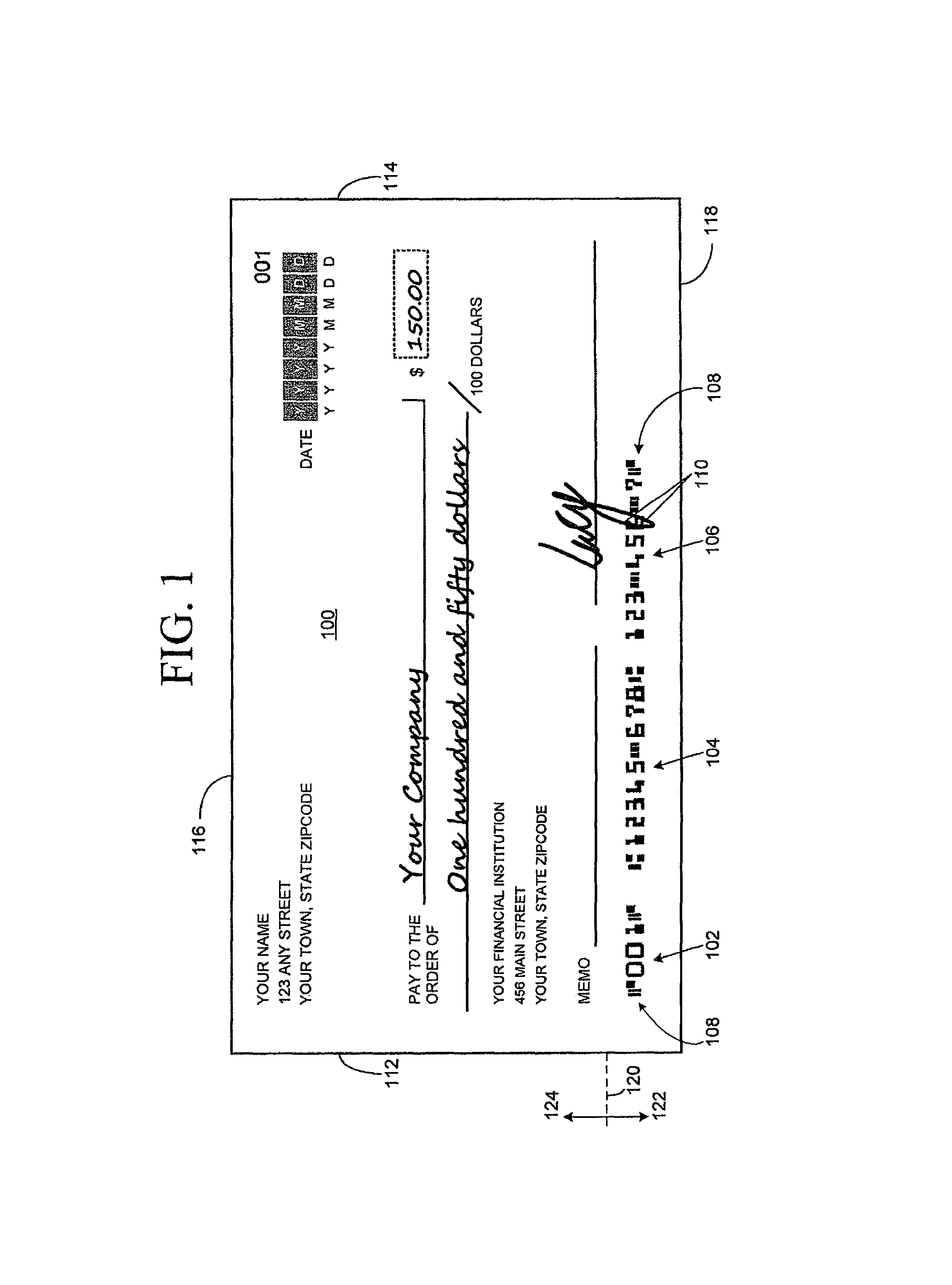
[0031]FIG. 1 is an illustration of a front of a sample personal check 100. MICR-encoded data 102, 104 and 106 have been printed in magnetic ink in a MICR-line 108 of check 100 using characters of a MICR font. A mark 110 made by pen ink is visible in MICR-line 108 and partially obscures MICR-encoded data 106. Since the pen ink is not magnetic ink, mark 110 is unlikely to adversely affect the readability of MICR-encoded data 106 by a magnetic reader machine.

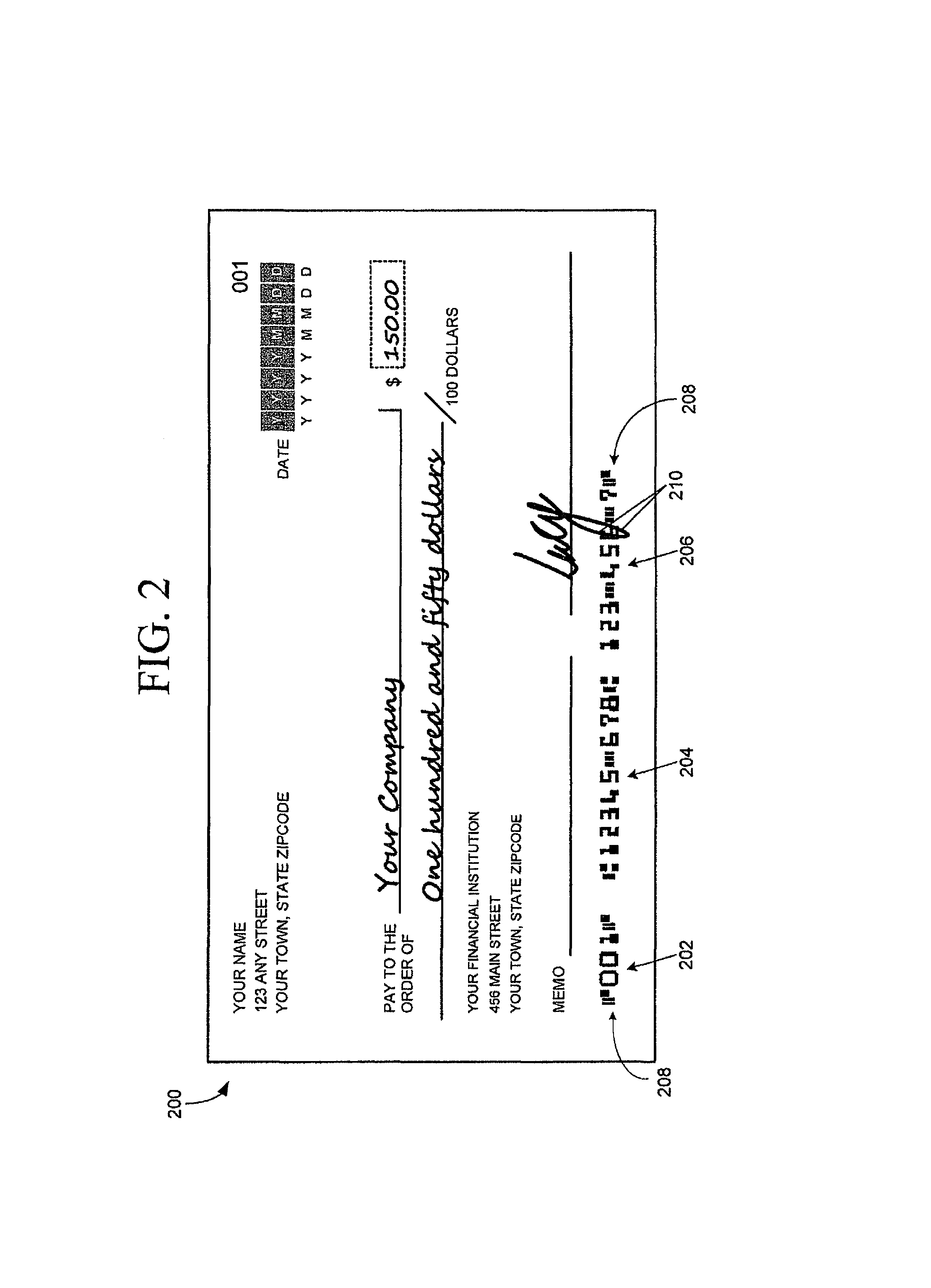
[0032]FIG. 2 is an illustration of a digital image 200 of the front o...


PUM


Abstract

A payment item having a magnetic ink character recognition (MICR)-line on its front is handled by generating, using visible light, a front image of the front of the payment item, generating, using infrared light, an infrared image of the front of the payment item or of a portion of the front of the payment item containing its MICR-line, and performing optical character recognition on the infrared image to identify data encoded in the MICR-line.

Description

BACKGROUND OF THE INVENTION[0001]Checks, money orders, bank drafts and other payment items are processed using Magnetic Ink Character Recognition (MICR) technology. In the case of checks, the MICR-encoded data may include an identification of the bank or institution that issued the check and the account number on which the check was drawn.[0002]In general, data is encoded on a document by printing characters of a specialized font, for example, E-13B or CMC-7, on the document using magnetic ink or toner. The MICR characters are printed in a section of the document reserved for that use, often called the “MICR-line”. A magnetic reader machine processes the document by magnetizing the characters. Each character, when magnetized, produces a unique magnetic signal due to the character's shape. The magnetic signal is recognized by the magnetic reader machine, which identifies—or “reads”—the character that has produced the signal. Even when the MICR characters or blank portions of the MICR...

Claims


Application Information

Patent Timeline
Patent Type & Authority Patents(United States)
IPC IPC(8): G06K7/08G06K7/00G06K9/00G06V30/10
CPCG06K9/2018G06K9/2054G06Q20/042G07D7/04G07D7/12G07D7/122G07D7/1205G06V30/2253G06V30/10G06V30/1429G06V30/1444
Inventor HUANG, JUNG-CHIH
Owner AMBIR TECH
Why Eureka
Try Eureka