Eureka AIR delivers breakthrough ideas for toughest innovation challenges, trusted by R&D personnel around the world.

Athletic wear

a technology for athletes and clothes, applied in the field of athletes, can solve the problems of difficulty in keeping the advantageous posture and not considering actively keeping the advantageous posture in water, and achieve the effect of reducing the offset position

Active Publication Date: 2013-02-26
ASICS CORP
View PDF46 Cites 45 Cited by
  • Summary
  • Abstract
  • Description
  • Claims
  • Application Information

AI Technical Summary

Benefits of technology

[0078]The advantage of the present invention is achieved by pressure and moment that the wear applies to the pelvis of the wearer during wearing. So, normally, the following measure needs to be employed: first, dressing a mannequin in the wear, and then measuring pressure distribution over the surface of the mannequin, and considering the measured value as parameter. However, in the above measurement of the pressure distribution, obtained data differs when using different types of mannequin. So, in the specification herein, the elastic modulus of the clothing fabric is employed as parameter.
[0079]It may be preferable that the average width of the belt front part in the vertical direction is about from 3 to 12 cm, and about from 4 to 10 cm may be more preferable as the average width.
[0080]Meanwhile, it may be preferable that the average width of the belt back part in the vertical direction is about from 5 to 12 cm, and about from 6 to 10 cm is more preferable as the average width.
[0081]When the width of the first belt part is too much large, the advantage of offset position is difficult to be achieved. Meanwhile, when the width of the first belt part is too much small, pressure applies the wearer locally and excessively.
[0082]In the present invention, it is preferable that the front upper edge line of the belt front part is formed to be convexed downward, and the back upper edge line of the belt back part is formed as being convexed upward or being generally horizontal.
[0083]Since the upper edge of the first belt part is formed as described above, the front upper edge line of the first belt part curves gently as extending from the center of the back surface toward the center of the front surface through the side parts, and the front upper edge line is a natural line.

Problems solved by technology

However, when the muscle is getting tired, it is difficult to keep the advantageous posture.
However, it does not consider actively keeping the advantageous posture in water.

Method used


Image

  • Athletic wear
  • Athletic wear
  • Athletic wear

Examples


first embodiment

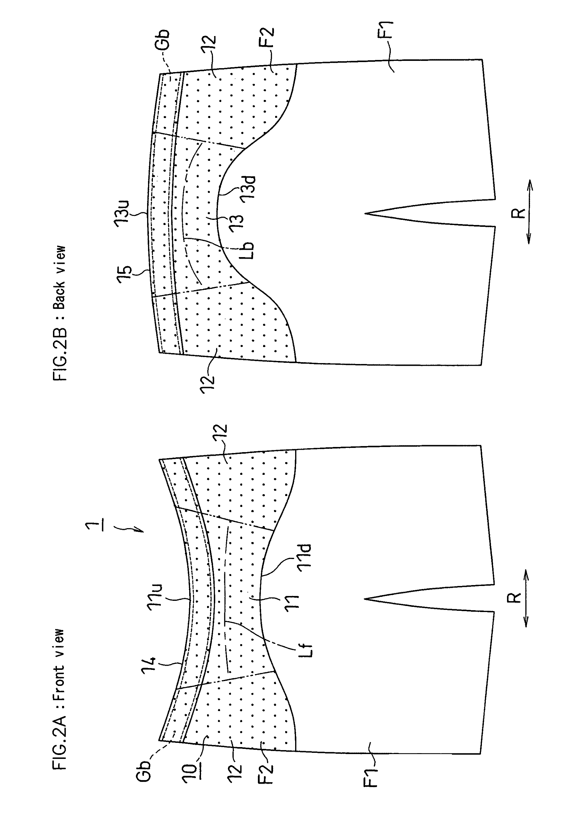
[0160]A first embodiment of the present invention is described below with reference to FIG. 1A, FIG. 2A, FIG. 2B and FIGS. 4A to 5C.

[0161]In FIG. 4B, a pelvis Bh comprises an ilium Bt and a sacrum Bs. A thighbone Bf connects to the pelvis Bh via a hip joint J.

[0162]Whole Structure:

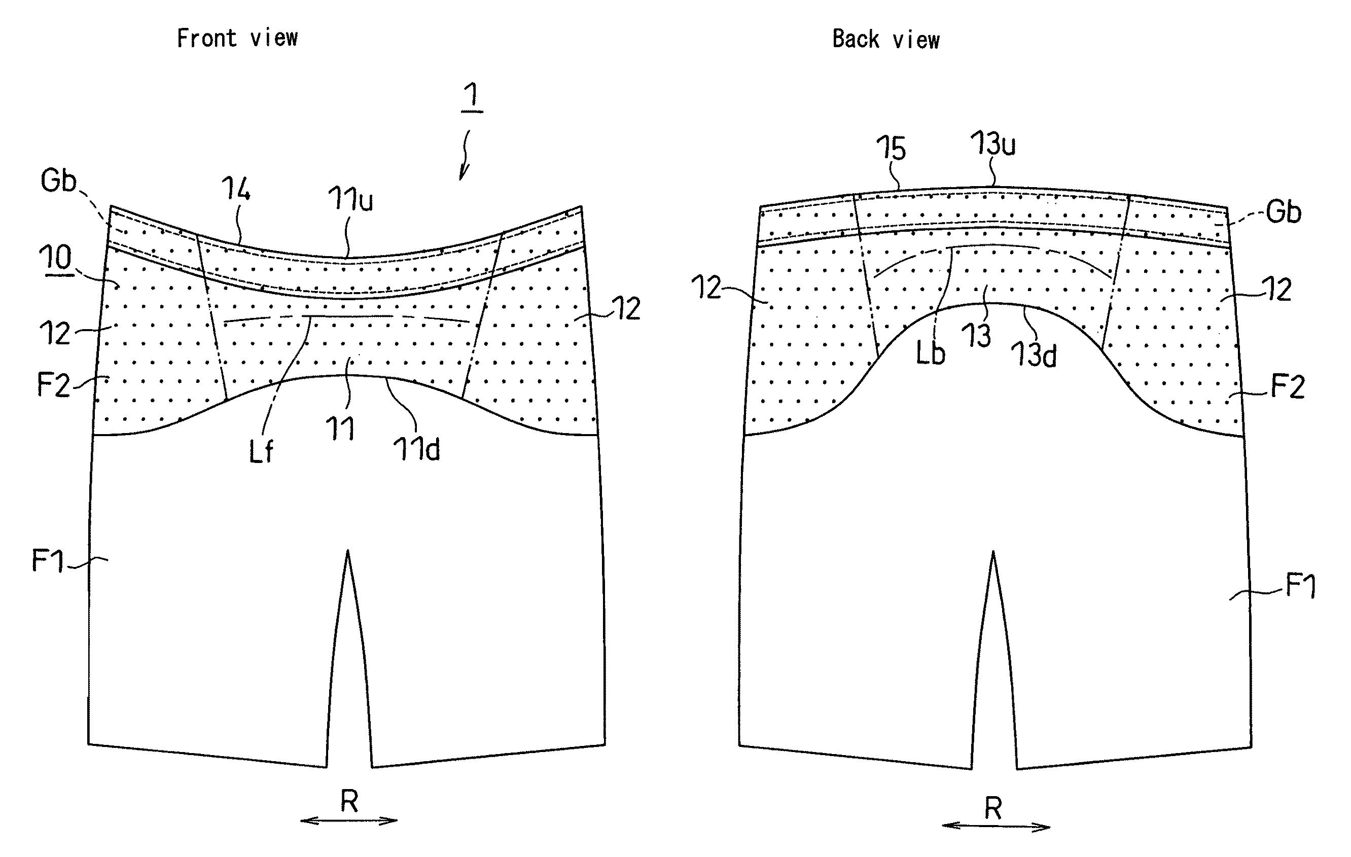
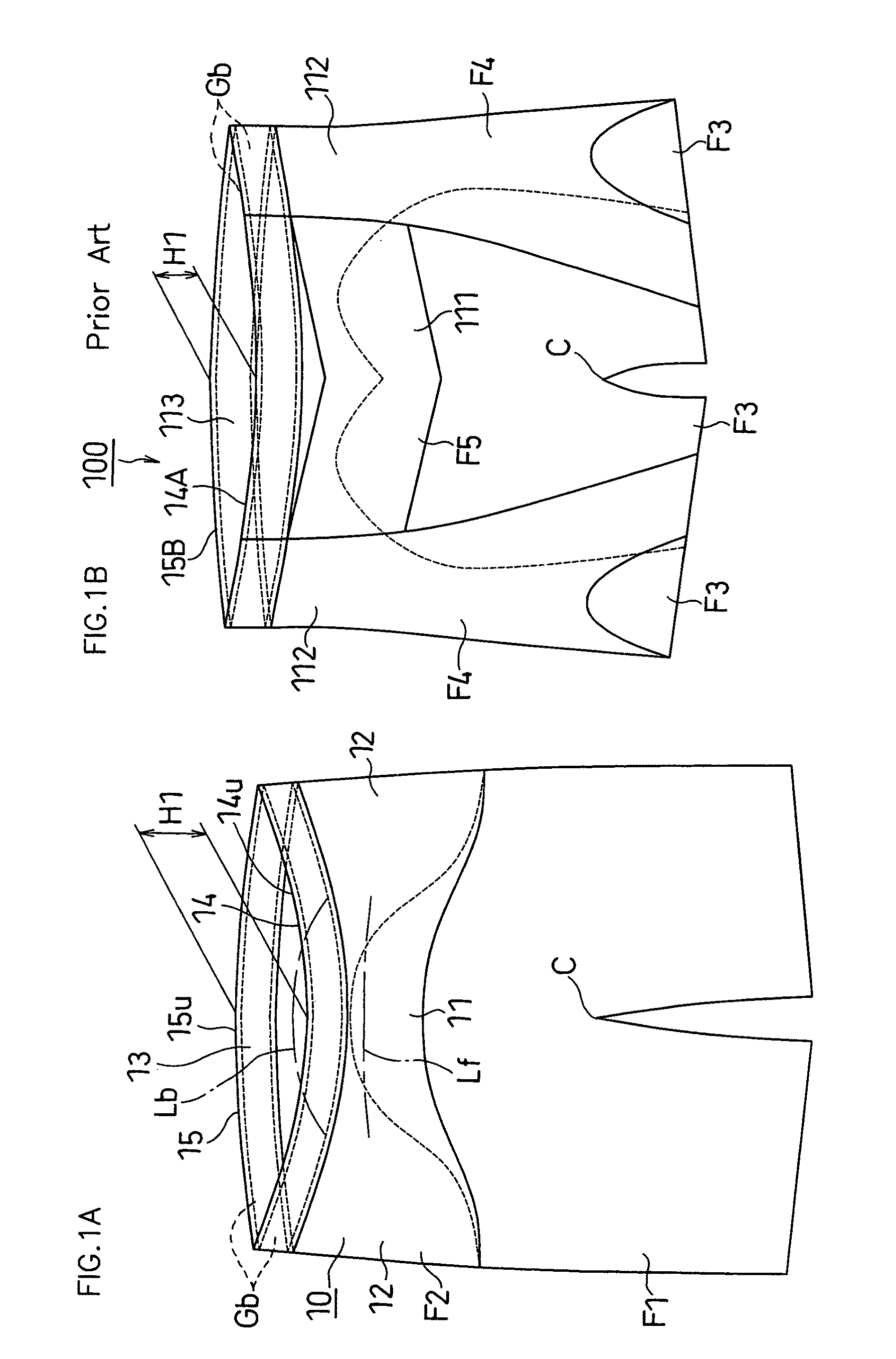
[0163]FIG. 1A shows a knee-length pants-type athletic wear 1.

[0164]As shown in FIG. 1A, the athletic wear 1 consists of clothing fabrics F1 and F2 that each has flexibility.

[0165]As shown in FIG. 2A and FIG. 2B, the athletic wear 1 is formed of the first clothing fabric F1 having small elastic modulus and the second clothing fabric F2 having larger elastic modulus than the first clothing fabric F1 (the second clothing fabric F2 is shown by rough dots).

[0166]As shown in FIG. 5A, FIG. 5B and FIG. 5C, when the wear 1 is worn, the first clothing fabric F1 covers circumference of lower part of a crotch C and the pelvis Bh, and the second clothing fabric F2 covers circumference of upper part of the pelvis Bh. Th...

third embodiment

[0188]A third embodiment of the present invention is described below with reference to FIG. 7A, FIG. 7B and FIG. 7C.

[0189]As shown in FIG. 7B and FIG. 7C, an athletic wear 1B comprises a pair of second belt parts 22. The second belt parts 22 each is formed of a second clothing fabric F2, and elastic modulus E3 of the second clothing fabric F2 along longitudinal direction is larger than elastic modulus E1 of a first clothing fabric F1.

[0190]Upper edge of the second belt parts 22 each has a first connection part 31 that is connected to a lower edge of a first belt part 10 at a posterior thigh Tb in lateral side of a pelvis Bh (FIG. 5B). The second belt part 22 is formed as belt-like extending from the first connection part 31 to medial side K1 of a knee K. Meanwhile, as shown in FIG. 7A, the second belt part 22 is not arranged over an anterior thigh Tf.

[0191]And, elastic modulus E3 of the second clothing fabric F2 along the longitudinal direction and elastic modulus E2 of the second c...

forth embodiment

[0193]A forth embodiment of the present invention is described below with reference to FIG. 8A, FIG. 8B and FIG. 8C.

[0194]As shown in FIG. 8A and FIG. 8C, an athletic wear 1C comprises a pair of third belt parts 23. The third belt parts 23 each is formed of a second clothing fabric F2, and elastic modulus E3 of the second clothing fabric F2 along longitudinal direction is larger than elastic modulus E1 of a first clothing fabric F1.

[0195]The third belt parts 23 is formed as belt-like extending from medial side Tu of a vicinity of an upper edge of an anterior thigh Tf to lateral side K2 of a knee K.

[0196]And, elastic modulus E3 of the second clothing fabric F2 along the longitudinal direction and elastic modulus E2 of the second clothing fabric F2 along waistline are the same value.

[0197]The other structures are similar to those of the third embodiment, for which like members are denoted by like reference numerals and will not be further described below.


PUM


Abstract

An athletic wear 1 of the present invention is formed of first clothing fabric F1 having small elastic modulus and second clothing fabric F2 having larger elastic modulus than first clothing fabric F1. First belt part 10 is formed by second clothing fabric covering circumference of upper part of pelvis Bh in wear 1. First belt part 10 essentially continuously comprises belt front part 11, belt back part 13 and pair belt side parts 12 covering upper part of pelvis Bh. Upper edge line of belt part slopes as extends from center of belt back part to center of belt front part.

Description

TECHNICAL FIELD[0001]The present invention relates to an athletic wear improving an athletic performance of an athlete and, particularly, it is preferred to be employed as a swimwear (bathing suit).BACKGROUND ART[0002]A profile drag is the largest drag that the athletes encounter in water. The profile drag is influenced by a project area, which is seen from an anterior view of the traveling direction, of the athlete. Therefore, keeping a posture of the athlete parallel to water surface as far as possible is advantageous in order to reduce the profile drag. That is, it is desirable to prevent positions of the waist, knees and toes of the athlete from sinking relative to a position of the head of the athlete during swimming, and to keep the whole body posture parallel and straight to water surface as far as possible.[0003]However, the athlete's posture tends to be unstable because of the action of gravity and buoyancy applying to the axis of the athlete. Meanwhile, the lower body has ...

Claims


Application Information

Patent Timeline
Patent Type & Authority Patents(United States)
IPC IPC(8): A41B9/00
CPCA41D7/00A41D27/00A41D13/0015A41D7/005A41D2400/24A41D31/18
Inventor TAKAMOTO, YOSHIKUNICHINEN, MAKOTOTSUJI, YOSHIEHASHIMOTO, YUJIOMURO, MAMORU
Owner ASICS CORP
Why Eureka
Eureka Blog
Learn More