Multi-column electron beam exposure apparatus and magnetic field generation device

a generation device and electron beam technology, applied in the field of multi-column electron beam exposure apparatus and magnetic field generation device, can solve the problems of increasing the amount of heat generated by the coil, using the multiple column cell, and a large mask size of around 300 mm, so as to prevent the generated magnetic field from leaking to the outside, increase the magnetic field strength, and strong magnetic field

Active Publication Date: 2013-03-05
ADVANTEST CORP
View PDF21 Cites 11 Cited by
  • Summary
  • Abstract
  • Description
  • Claims
  • Application Information

AI Technical Summary

Benefits of technology

[0009]The present invention has been made in view of the above problem, and aims to provide a multi-column electron beam exposure apparatus and a magnetic field generation device which are capable of generating a strong magnetic field in a small space so that the intervals between column cells can be made small.
[0013]The multi-column electron beam exposure apparatus of the present invention uses permanent magnets for the generation of magnetic fields to converge an electron beam in each column cell. As permanent magnets having magnetic field strength high enough to converge the electron beam, a neodymium magnet is used, for example. Use of such a permanent magnet allows reduction in the size of the magnetic field generation unit, whereby the intervals between the column cells can be reduced to 25 mm or smaller, for example. As a result, many column cells can be used within an area of 150 mm2 or smaller, and the throughput can be improved.
[0014]In addition, each permanent magnet is surrounded by the frame made of a ferromagnetic material such as pure iron. This makes it possible to prevent one column cell from affecting the magnetic fields of the lenses in other adjacent column cells. Accordingly, the accuracy of the exposure by each column cell can be secured.
[0018]In the magnetic field generation device of the present invention, magnetic fields are generated by using rare-earth permanent magnets such as neodymium magnets or samarium-cobalt magnets. These permanent magnets are configured by two annular permanent magnets magnetized in a direction perpendicular to the radial direction thereof to generate magnetic fields. In particular, by disposing the permanent magnets with their magnetization directions opposite to each other, the magnetic field strength increases, whereby a strong magnetic field can be generated in a small space.
[0019]In addition, each permanent magnet is surrounded by the frame made of a ferromagnetic material such as pure iron. This makes it possible to prevent a generated magnetic field from leaking to the outside. Moreover, an electromagnetic coil is provided near each permanent magnet, and therefore, the magnetic field strength of the permanent magnet can be adjusted by use of the magnetic field of the electromagnetic coil.

Problems solved by technology

However, use of the multiple column cells as above entails involves the following limitations.
Also, the mask of such a large size as around 300 mm2 is unacceptable in consideration of the handling and storing of CP masks and wafers.
However, such measures may increase the amounts of heat generated by the coils, and possibly break the coils.

Method used


Image

  • Multi-column electron beam exposure apparatus and magnetic field generation device
  • Multi-column electron beam exposure apparatus and magnetic field generation device
  • Multi-column electron beam exposure apparatus and magnetic field generation device

Examples


example 1

of Configuration of Electron Beam Converging Unit

[0059]FIGS. 7A and 7B are cross-sectional views of an electron beam converging unit 70, taken along a line extending along and being parallel to the optical axis C of the electron beam converging unit 70. FIG. 7A shows magnetic fields with magnetic field lines, and FIG. 7B shows the strength of the magnetic fields.

[0060]As shown in FIGS. 7A and 7B, the electron beam converging unit 70 is formed of a ferromagnetic frame 71 made of pure iron or the like, and permanent magnets PA and PB and electromagnetic coils EC1 and EC2 all surrounded by the ferromagnetic frame 71. The permanent magnets PA and PB are two permanent magnets each formed in a ring shape (annular shape) and magnetized in the Z-axis (optical axis C) direction. These two permanent magnets PA and PB are disposed one above the other with their same polarities facing each other. The two permanent magnets PA and PB are so disposed as to allow a gap therebetween as small as poss...

example 2

of Configuration of Electron Beam Converging Unit

[0066]FIGS. 8A and 8B show another example of a configuration of each electron beam converging unit. FIGS. 8A and 8B are cross-sectional views of an electron beam converging unit 80, taken along a line extending along and being parallel to the optical axis C of the electron beam converging unit 80. FIG. 8A shows magnetic fields with magnetic field lines, and FIG. 8B shows the strength of the magnetic fields.

[0067]Two permanent magnets are used in the electron beam converging unit 80 shown in FIGS. 8A and 8B as in the case of the electron beam converging unit 70 shown in FIGS. 7A and 7B, but the arrangement of the magnets is different.

[0068]Permanent magnets PC and PD each formed in a ring shape (annular shape) are magnetized in the Z-axis (optical axis C) direction. These two permanent magnets PC and PD are arranged in such a manner that the polarities thereof are oriented in the same direction. A gap is provided between the permanent...

example 3

of Configuration of Electron Beam Converging Unit

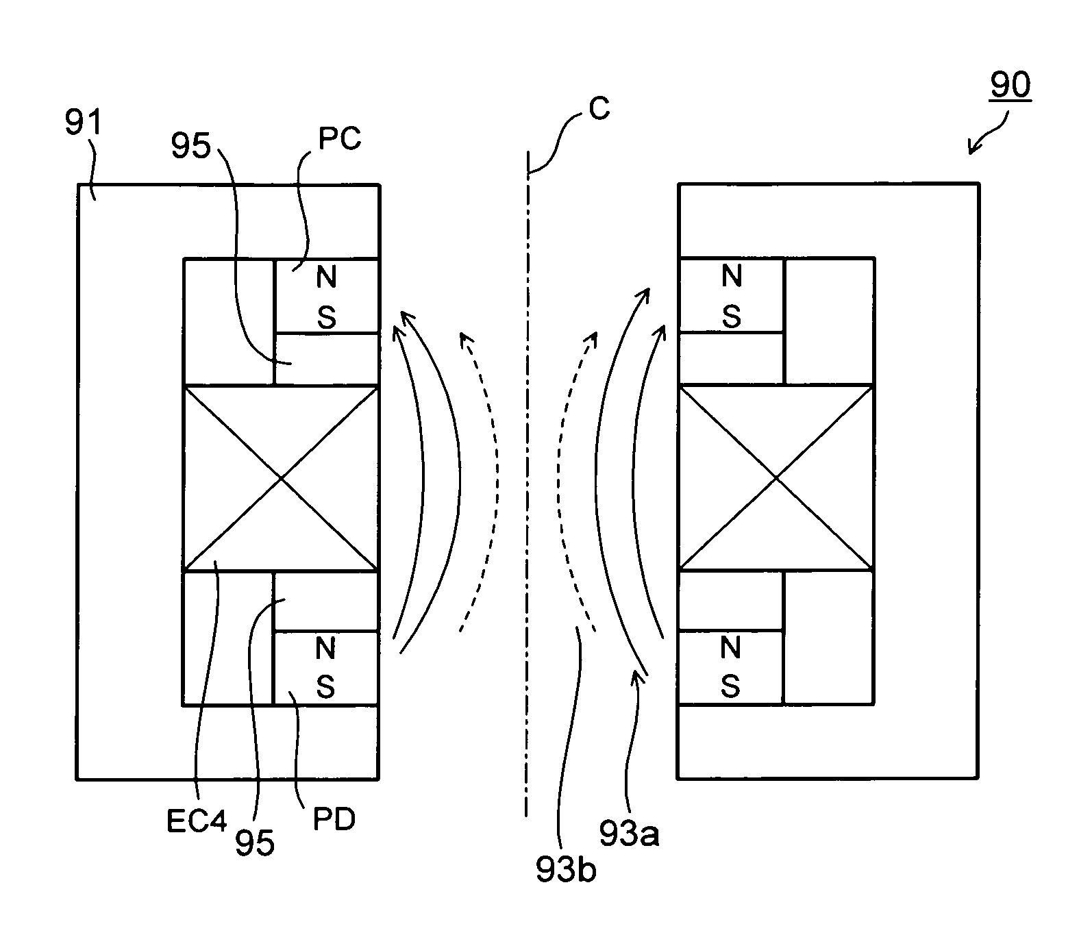
[0075]FIGS. 9A and 9B show still another example of a configuration of each electron beam converging unit. FIGS. 9A and 9B are cross-sectional views of an electron beam converging unit 90, taken along a line extending along and being parallel to the optical axis C of the electron beam converging unit 90. FIG. 9A shows magnetic fields with magnetic field lines, and FIG. 9B shows the strength of the magnetic fields.

[0076]Two permanent magnets and one electromagnetic coil for correction are used in the electron beam converging unit 90 shown in FIGS. 9A and 9B as in the case of the electron beam converging unit 80 shown in FIGS. 8A and 8B, but the arrangement of the correction electromagnetic coil is different.

[0077]The permanent magnets PC and PD each formed in a ring shape (annular shape) are magnetized in the Z-axis (optical axis C) direction. These two permanent magnets PC and PD are arranged in such a manner that the polarities there...


PUM


Abstract

A multi-column electron beam exposure apparatus includes: multiple column cells; an electron beam converging unit in which two annular permanent magnets and electromagnetic coils are surrounded by a ferromagnetic frame, the two annular permanent magnets being magnetized in an optical axis direction and symmetrical about the optical axis, where the electromagnetic coils adjust magnetic fields of the annular permanent magnets; and a substrate provided with circular apertures through which electron beams used in the column cells pass, respectively, where the electron beam converging unit is disposed in each of the circular apertures. The two annular permanent magnets may be disposed one above the other in the optical axis direction, and the electromagnetic coils may be provided inside or outside the annular permanent magnets in their radial direction.

Description

CROSS-REFERENCE TO RELATED APPLICATIONS[0001]This application is a continuation of prior International Patent Application No. PCT / JP2008 / 061431, filed Jun. 24, 2008, the entire contents of which are incorporated herein by reference.BACKGROUND OF THE INVENTION[0002]1. Field of the Invention[0003]The present invention relates to a multi-column electron beam exposure apparatus and a magnetic field generation device, and particularly relates to a multi-column electron beam exposure apparatus and a magnetic field generation device which are capable of generating a strong magnetic field in a small space so that the intervals between column cells can be made small.[0004]2. Description of the Related Art[0005]For the purpose of improving throughput, an electron beam exposure apparatus is provided with a variable rectangular aperture or multiple stencil mask patterns (character projection (CP)) in a stencil mask, and transfers a desired pattern onto a wafer through exposure by selectively us...

Claims


Application Information

Patent Timeline
Patent Type & Authority Patents(United States)
IPC IPC(8): H01J25/50
CPCB82Y10/00B82Y40/00H01J37/06H01J37/143H01J37/3174H01J2237/0635H01J2237/14
Inventor YASUDA, HIROSHIOOAE, YOSHIHISAHARAGUCHI, TAKESHI
Owner ADVANTEST CORP
Why Eureka
Try Eureka