Imaging lens, optical apparatus equipped with imaging lens and method for manufacturing imaging lens

a technology of imaging lens and optical apparatus, which is applied in the field of imaging lens, can solve the problems of large amount of lens extension, difficult to build up a structure of the lens barrel, and difficult to control variations in spherical aberration and curvature of field

Active Publication Date: 2013-03-12
NIKON CORP
View PDF4 Cites 2 Cited by
  • Summary
  • Abstract
  • Description
  • Claims
  • Application Information

AI Technical Summary

Benefits of technology

[0008]It is an object of the present invention, which was devised in view of these problems, to provide a downsized imaging lens having a small moving amount upon shooting a close range object and getting various aberrations to be well corrected, an optical apparatus equipped with the imaging lens and a method for manufacturing the imaging lens.

Problems solved by technology

According to the prior art exemplified by Japanese Patent Application Laid-Open No. 7-181390, however, there is a large moving amount of especially a first lens group among the respective lens groups upon focusing, and it is difficult due to this large moving amount to be used for an interchangeable lens equipped with a drive mechanism within a lens barrel, which is conceived as a mainstream type of lens at the present.
Moreover, in the case of desiring a length of the lens barrel to be kept short upon focusing on an infinitely distant object and desiring a small-sized and compact lens barrel as well, a large amount of lens extension is hard to build up a structure of the lens barrel.
Moreover, in the case of reducing the moving amount of particularly the first lens group while accelerating the downsizing on the extension of the prior arts, it is difficult to control variations in spherical aberration and curvature of field due to focusing, and there is a necessity for further improvements.

Method used


Image

  • Imaging lens, optical apparatus equipped with imaging lens and method for manufacturing imaging lens
  • Imaging lens, optical apparatus equipped with imaging lens and method for manufacturing imaging lens
  • Imaging lens, optical apparatus equipped with imaging lens and method for manufacturing imaging lens

Examples


example 1

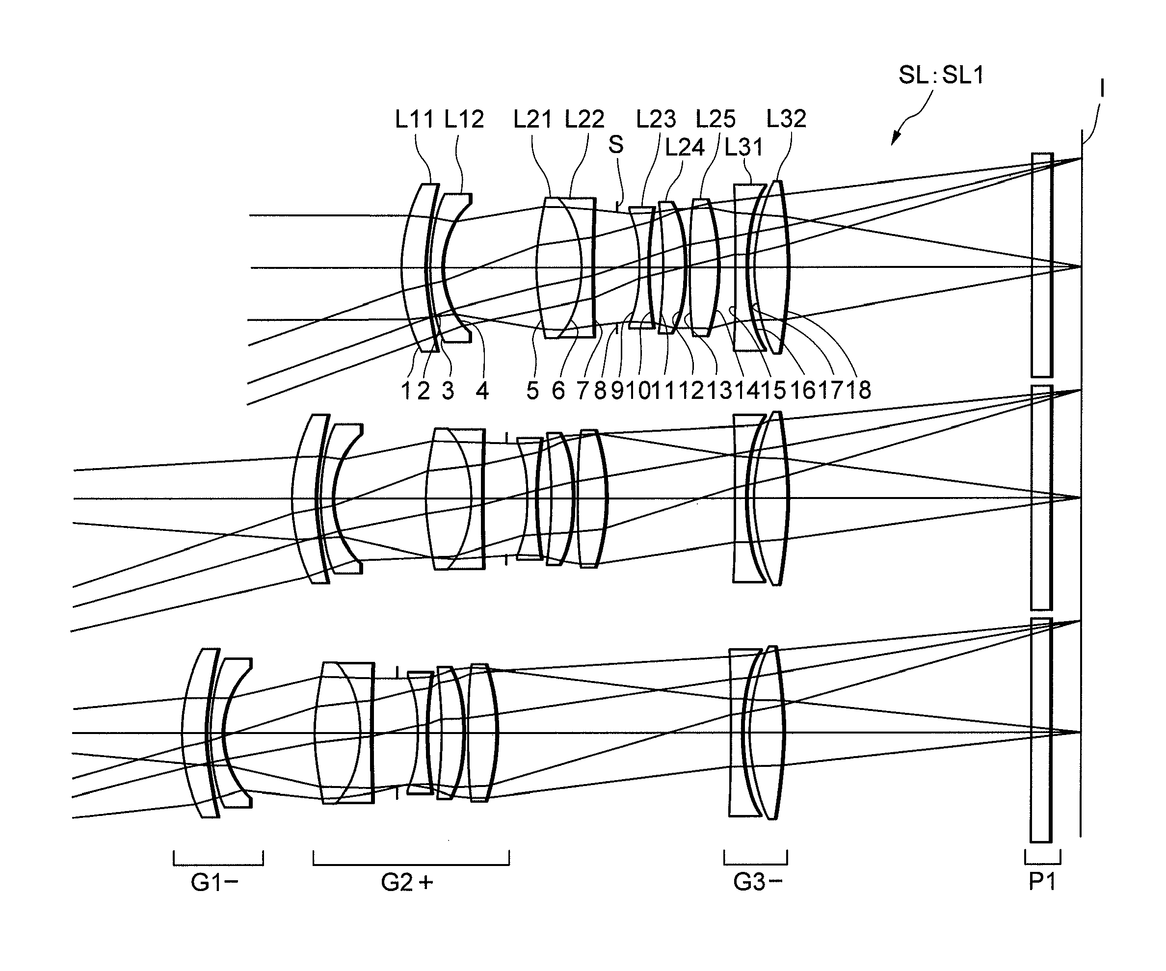
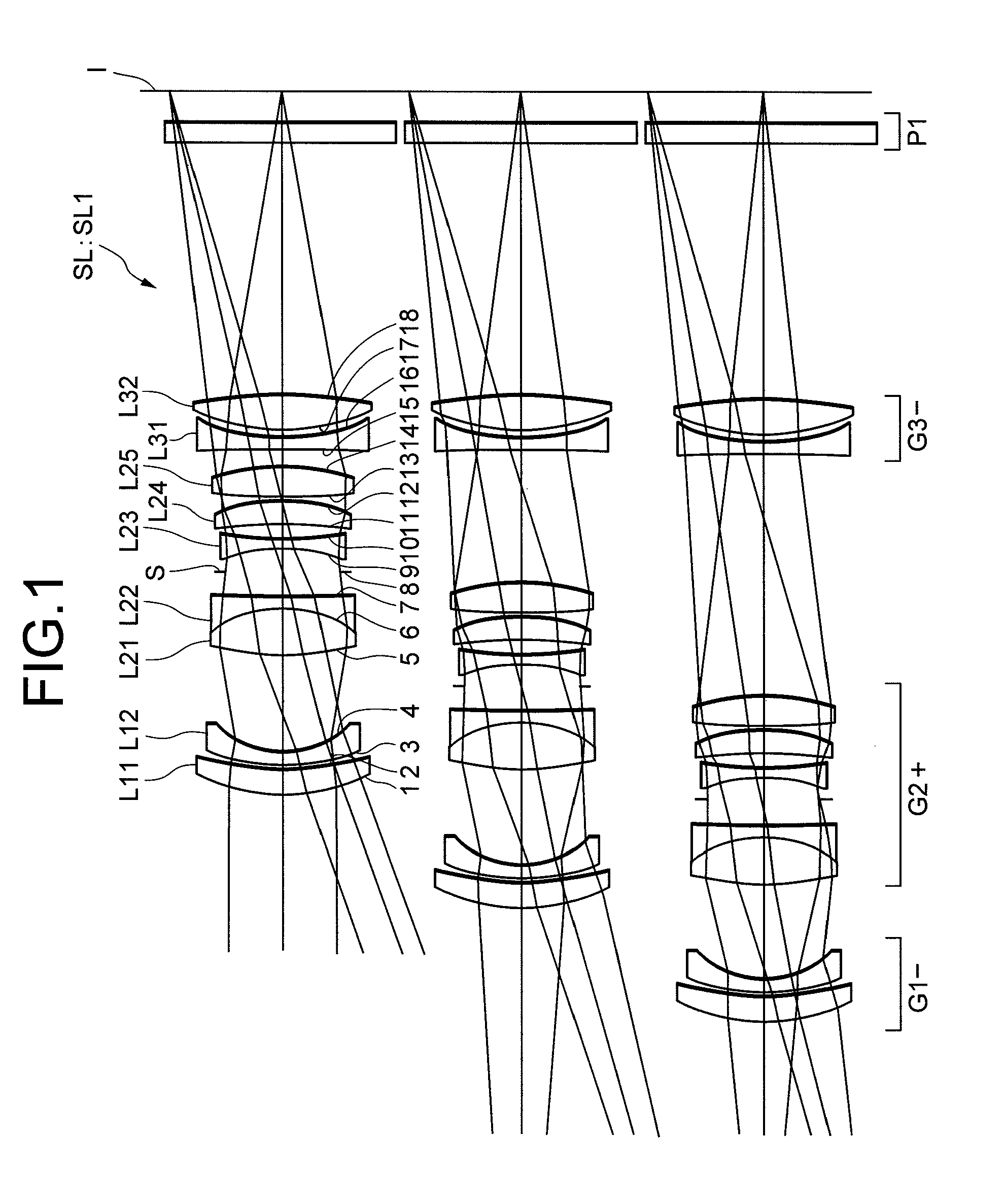
[0067]FIG. 1 is a view showing a configuration of an imaging lens SL1 according to Example 1. In the imaging lens SL1 in FIG. 1, a first lens group G1 is composed of, in order from an object side, two lens elements, i.e., a positive meniscus lens L11 with a convex surface facing the object side and a negative meniscus lens L12 with a convex surface facing the object side. A second lens group G2 having positive refractive power on the whole is composed of, in order from the object side, five lens elements such as a cemented lens constructed by a double convex lens L21 cemented with a double concave lens L22, an aperture stop S, a double concave lens L23, a positive meniscus lens L24 with a convex surface facing an image side and a double convex lens L25. A third lens group G3 having negative refractive power on the whole is composed of, in order from the object side, a double concave lens L31 and a double convex lens L32.

[0068]The following table 1 shows various items of data of the ...

example 2

[0073]FIG. 3 is a view showing a configuration of an imaging lens SL2 according to Example 2. In the imaging lens SL2 in FIG. 3, the first lens group G1 having negative refractive power on the whole is composed of, in order from the object side, two lens elements, i.e., a double concave lens L11 and a double convex lens L12. The second lens group G2 having positive refractive power on the whole is composed of, in order from the object side, five lens elements such as a cemented lens constructed by a double convex lens L21 cemented with a negative meniscus lens L22 with a concave surface facing the object side, an aperture stop S, a double concave lens L23, a positive meniscus lens L24 with a convex surface facing the image side and a double convex lens L25. The third lens group G3 having negative refractive power on the whole is composed of, in order from the object side, two lens elements such as a negative meniscus lens L31 with a concave surface facing the image side and a positi...

example 3

[0078]FIG. 5 is a view showing a configuration of an imaging lens SL3 according to Example 3. In the imaging lens SL3 in FIG. 5, the first lens group G1 having negative refractive power on the whole is composed of, in order from the object side, two lens elements, i.e., a double concave lens L11 and a double convex lens L12. The second lens group G2 having positive refractive power on the whole is composed of, in order from the object side, four lens elements such as a double convex lens L21, a negative meniscus lens L22 with a concave surface facing the image side, an aperture stop S and a cemented lens constructed by a double concave lens L23 cemented with a double convex lens L24. The third lens group G3 having negative refractive power on the whole is composed of, in order from the object side, two lens elements such as a negative meniscus lens L31 with a concave surface facing the image side and a double convex lens L32.

[0079]The following Table 3 shows values of various items ...


PUM

PropertyMeasurementUnit
refractive poweraaaaaaaaaa
distanceaaaaaaaaaa
focal lengthaaaaaaaaaa

Abstract

An imaging lens SL mounted in a single lens reflex digital camera 1 is composed of, in order from an object side, a first lens group G1 having negative refractive power, a second lens group G2 having positive refractive power, and a third lens group G3 having negative refractive power. Upon focusing on a near-distance object from an infinitely distant object, a configuration is that at least any one of the first lens group G1 and the second lens group G2 is moved to the object side to vary a distance between the first lens group G1 and the second lens group G2. Accordingly, a downsized imaging lens having a small moving amount upon shooting a close range object, in which various aberrations are well corrected is provided.

Description

[0001]The disclosure of the following priority application is herein incorporated by reference:[0002]Japanese Patent Application No. 2010-211657 filed on Sep. 22, 2010.BACKGROUND OF THE INVENTION[0003]1. Field of the Invention[0004]The present invention relates to an imaging lens, an optical apparatus equipped with the imaging lens, and a method for manufacturing the imaging lens.[0005]2. Related Background Art[0006]A macro (micro) lens has hitherto been proposed, which is capable of performing close range photography from an infinitely distant object up to a shooting magnification on the order of −1.0 (refer to, e.g., Japanese Patent Application Laid-Open No. 7-181390).[0007]According to the prior art exemplified by Japanese Patent Application Laid-Open No. 7-181390, however, there is a large moving amount of especially a first lens group among the respective lens groups upon focusing, and it is difficult due to this large moving amount to be used for an interchangeable lens equipp...

Claims


Application Information

Patent Timeline
Patent Type & Authority Patents(United States)
IPC IPC(8): G02B15/14G03B19/12
CPCG02B13/26G02B15/177Y10T29/49826G02B15/143503
Inventor MURATANI, MAMISATO, HARUOMOURI, MOTOHISA
Owner NIKON CORP
Why Eureka
Try Eureka