
Drive unit

a technology of drive unit and piezoelectric element, which is applied in the direction of generator/motor, instruments, cameras, etc., can solve the problems of significant deterioration in the performance of optical system, difficult to accurately carry out positional control of drive unit using such piezoelectric element, and tilting of movable objects, so as to achieve simplified control of drive signal switching and detection accurately

Active Publication Date: 2008-11-25
KONICA MINOLTA OPTO
View PDF6 Cites 2 Cited by
  • Summary
  • Abstract
  • Description
  • Claims
  • Application Information

AI Technical Summary

Benefits of technology

"The present invention provides a drive unit that can correct the tilting of a movable object caused when it makes contact with a restricting member, without the need for a sensor. The drive unit includes an electromechanical transducer, a supporting member, a movable object, an urging member, and a drive circuit. The drive circuit applies a first wave drive signal to the supporting member to vibrate it and allow the movable object to make contact with the restricting member, and then applies a second wave drive signal to move the movable object away from the restricting member. This allows for precise positioning of the movable object without the need for a sensor. The drive unit can also prevent displacement of the optical axis and ensure smooth movement of the movable object."

Problems solved by technology

However, it is difficult to accurately carry out positional control for the drive unit that uses such a piezoelectric element.
However, in the case that the movable object makes contact with the restricting member (the supporting section 3) and stopped, if the driving of the piezoelectric element is not stopped immediately after the movable object makes contact with the restricting member, there is a problem in which the movable object is tilted as shown in FIG. 4B.
Although the tilting of the movable object is very slight, in the case of the drive unit connected to an optical member, such as a lens 12, the tilting becomes a cause of significant deterioration in the performance of the optical system.
However, such a configuration in which the restricting member is made larger and a sensor is provided is not desirable from the viewpoint of downsizing the optical system, such as a lens barrel, in recent years.
Furthermore, providing a sensor causes a problem of increasing cost.

Method used


Image

  • Drive unit
  • Drive unit
  • Drive unit

Examples


Embodiment Construction

[0060]Before the description of the present invention proceeds, it is to be noted that like parts are designated by like reference numerals throughout the accompanying drawings. A drive unit according to an embodiment of the present invention will be described below referring to the drawings.

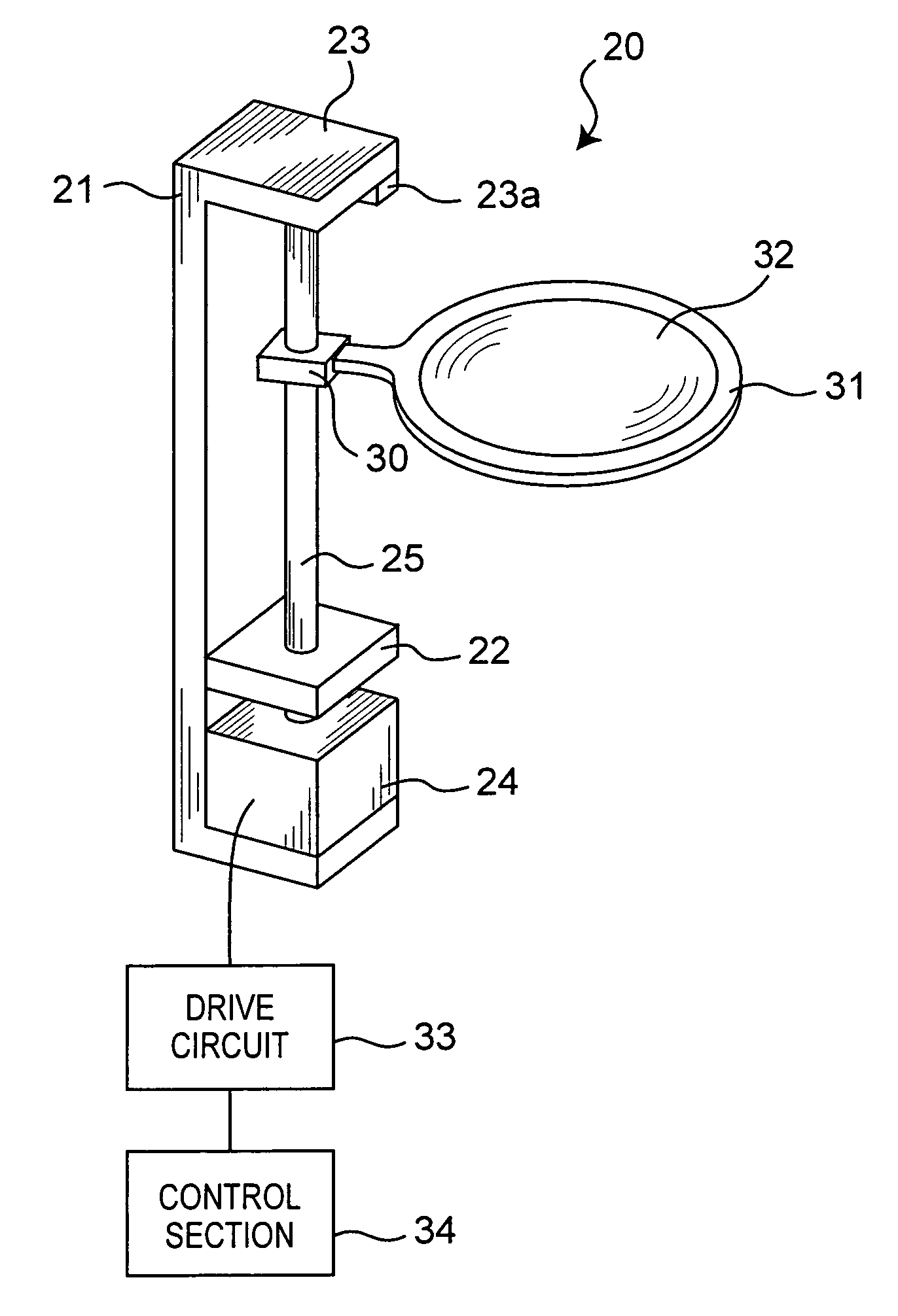
[0061]FIG. 5A is a schematic view showing a configuration of a drive unit according to this embodiment of the present invention. The drive unit 20 according to this embodiment is used to drive a lens frame 31 in which an optical lens 32 being used in a lens barrel of a camera is provided. The optical lens 32 driven using the drive unit is used as a zoom lens in the lens barrel of a camera to adjust the focal length of the camera when driven in its movable range. In this lens barrel, one end of the movable range is a tele-position where the focus of the lens barrel is the longest, and the other end is a macro-position where the focus of the lens barrel is the shortest.

[0062]The drive unit 20 driv...


PUM


Abstract

A drive unit being characterized in that a movable object can be prevented from being tilted when the movable object is stopped using a restricting member. The drive unit comprises a piezoelectric element; a rod provided at an end of the piezoelectric element; a movable object, which is frictionally engaged with the rod and the movable range of which is restricted using the restricting members; and drive pulse generating means for applying drive signals to the piezoelectric element, wherein the drive pulse generating means apply a first wave drive signal for vibrating the rod so that the movable object moves toward the restricting member when the movable object is moved to a position where the movable object is close to the restricting member, and temporarily apply a second wave drive signal for vibrating the rod so that the movable object is moved in a direction of movement away from the restricting member after the movable object is made contact with the restricting member, and then stop the application of the drive signal.

Description

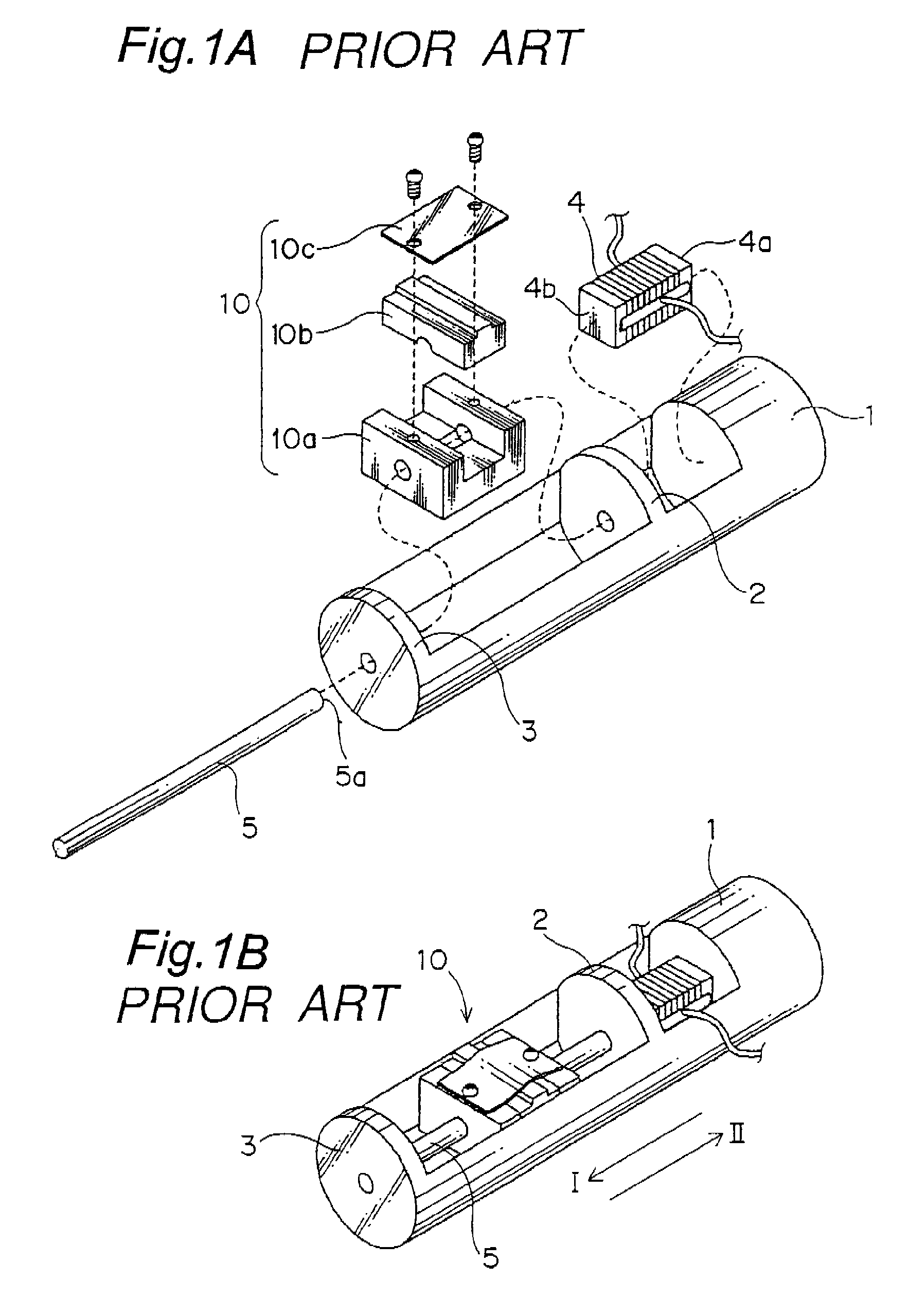
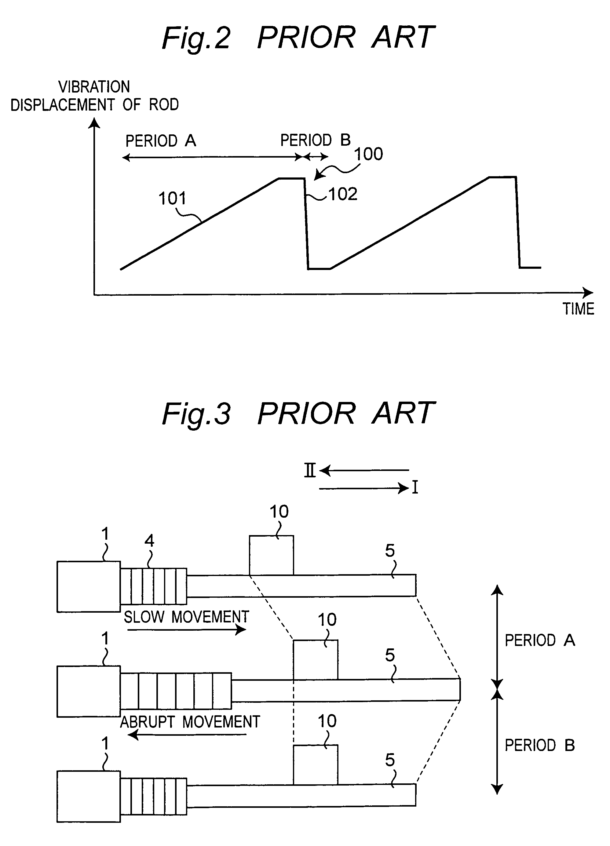
BACKGROUND OF THE INVENTION[0001]The present invention relates to a drive unit for driving a movable object incorporating mainly an optical component, such as a lens being used in a camera, a DVD drive, a CD drive, an MD drive, an endoscope or the like.[0002]As a drive unit that uses an electromechanical transducer, such as a piezoelectric element, which changes its dimension (expands or contracts) when a voltage is applied, the drive unit shown in an exploded perspective view in FIG. 1A and in an assembled perspective view in FIG. 1B, for example, is known (U.S. Pat. No. 6,016,231).[0003]A piezoelectric element 4 comprises multiple piezoelectric plates stacked. One end 4a thereof in the expansion / contraction direction is secured to a base 1, and the other end 4b thereof is secured to the first end 5a of a rod (supporting member) 5. The rod 5 is slidably supported on supporting sections 2 and 3 integrated with the base 1.[0004]The rod 5 is held between the main unit 10a and the cap ...

Claims


Application Information

Patent Timeline
Patent Type & Authority Patents(United States)
IPC IPC(8): H01L41/09H10N30/20H02N2/00
CPCH02N2/025H02N2/067
Inventor NAMIKAWA, TAKETOYUASA, TOMOYUKINAKANO, HARUYUKIOKAMOTO, YASUHIRO
Owner KONICA MINOLTA OPTO
Learn More