Optical head

a technology of optical head and tilting, which is applied in the field of tilting detector, can solve the problems of large increase in assembly steps and component cost, difficult to reduce the size and thickness of the optical head, and large variation in the amount of light received by the photodetectors, so as to reduce the size and thickness, excellent responsiveness, and correct the tilt

Inactive Publication Date: 2006-01-12
PANASONIC CORP
View PDF19 Cites 8 Cited by
  • Summary
  • Abstract
  • Description
  • Claims
  • Application Information

AI Technical Summary

Benefits of technology

[0018] With the foregoing in mind, it is an object of the present invention to provide an optical head that can detect a tilt without requiring a special light source for tilt detection, reduce both size and thickness, and correct the tilt with excellent responsiveness.

Problems solved by technology

In the conventional tilt detector of the optical head, however, variations in the angle of divergence or the emission point of the LED 84 are increased excessively, which leads to a larger variation in the amount of light received by the photodetectors 85a, 85b.
Thus, it is difficult to reduce the size and thickness of the optical head 81, and the assembly steps and the component cost are raised considerably.
Therefore, the optical head 81 including the tilt corrector becomes larger in size, and thus it is difficult to reduce the size of the disk recording / reproducing apparatus.
Thus, the tilt correction of the optical head 81 requires a waiting time for the system, so that a tilt cannot be detected in real time at high speed during recording or reproduction.
Consequently, it is not possible to achieve tilt correction with excellent responsiveness.

Method used


Image

  • Optical head
  • Optical head
  • Optical head

Examples


embodiment 1

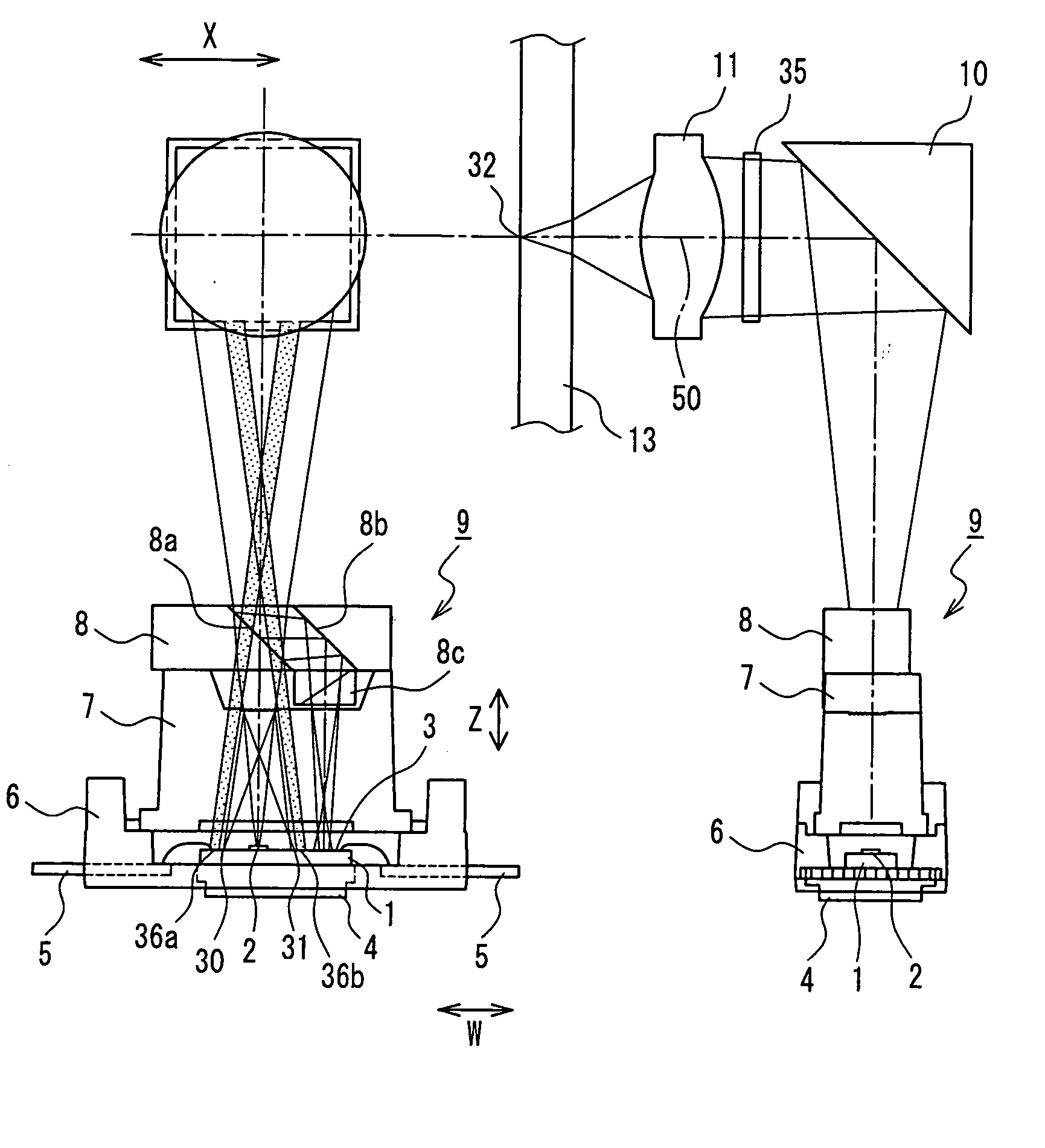
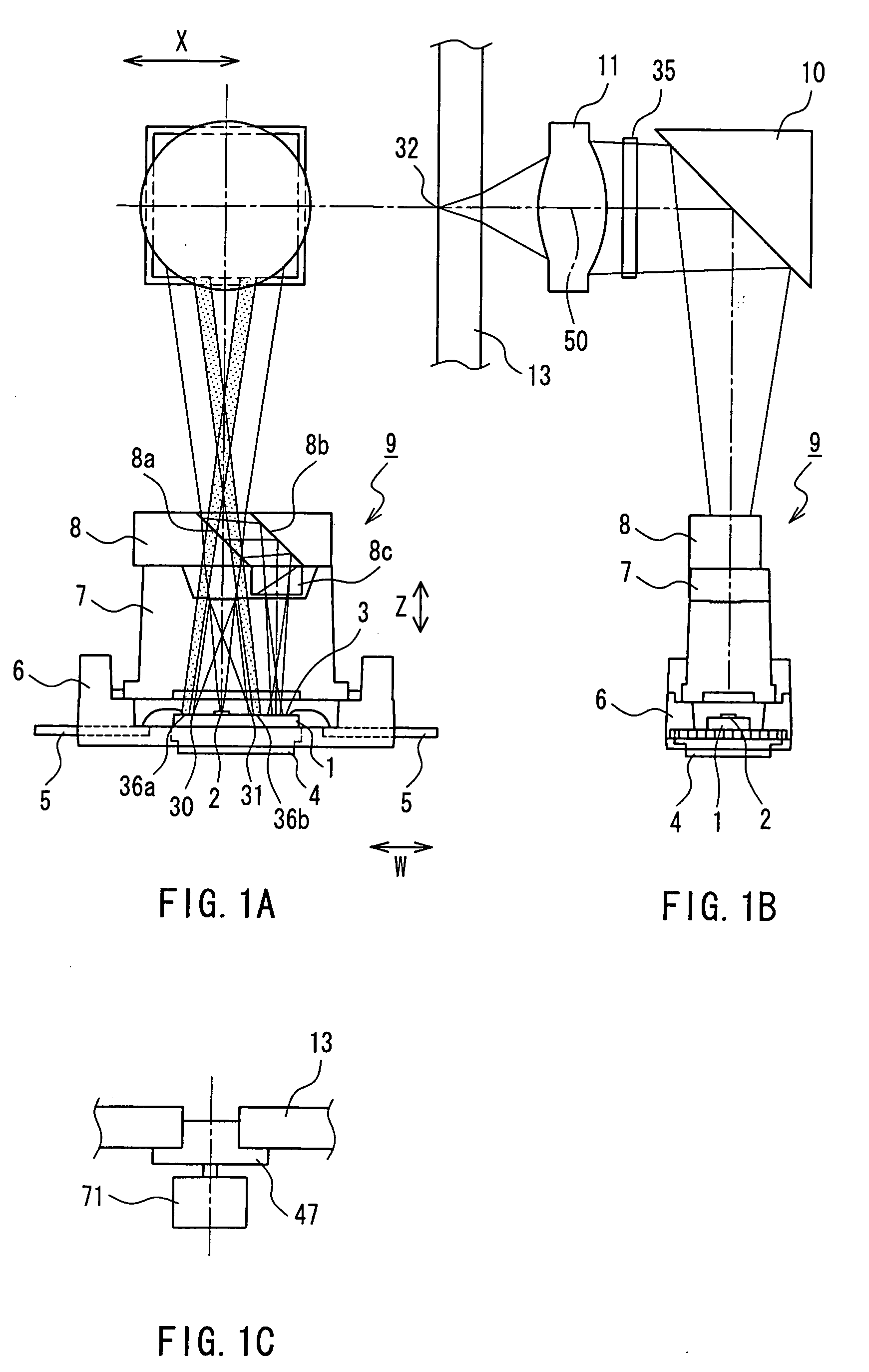
[0107]FIG. 1 shows the configuration of an optical head in Embodiment 1 of the present invention. FIG. 1A is a plan view of the optical head, and FIG. 1B is a side view of the optical head in FIG. 1A. FIG. 1C is a side view showing the vicinity of a central portion of a magneto-optical recording medium.

[0108] Reference numeral 1 is a silicon substrate, 2 is a semiconductor laser that is fixed on the silicon substrate 1 and corresponds to a light source, 3 is a multisegment photodetector that is formed on the silicon substrate 1 by an IC process, and 4 is a thermal conductive plate that maintains the silicon substrate 1 in the state of heat conduction via silver paste.

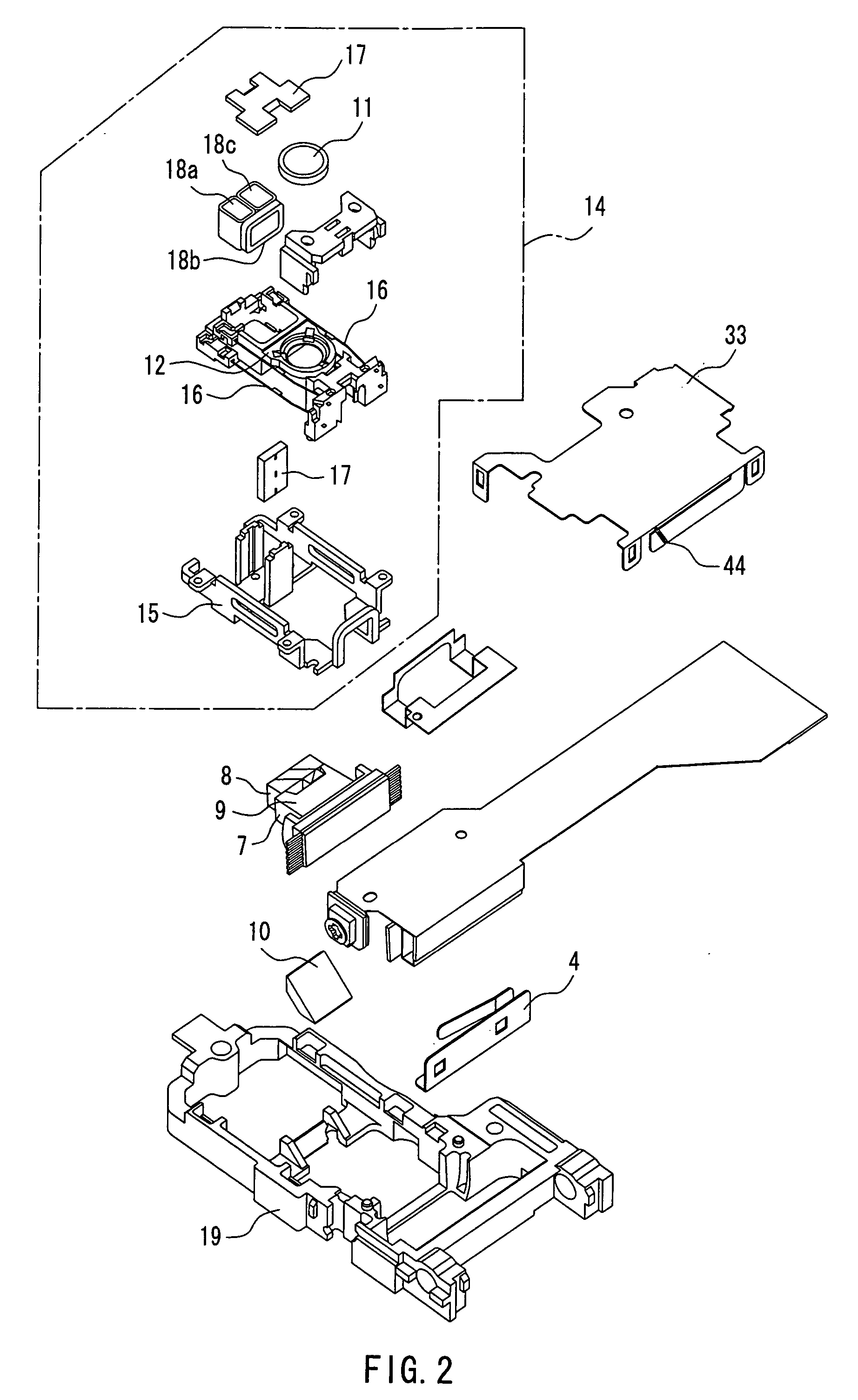
[0109] Reference numeral 5 is a terminal that is connected to the multisegment photodetector 3 by wire bonding or the like, 6 is a resin package that holds the silicon substrate 1, the thermal conductive plate 4, and the terminal 5, 7 is a hologram element (diffraction grating) that is made of resin, 8 is a composite ...

embodiment 2

[0187] Embodiment 2 will be described by referring to FIG. 12. FIG. 12 includes an exploded perspective view showing a tilt detector of an optical head in Embodiment 2 and a block diagram showing the process of outputting a tilt correction signal. The identical elements to those in FIG. 5 of Embodiment 1 are denoted by the same reference numerals, and a detailed explanation will not be repeated.

[0188] In Embodiment 2, the regions of the diffraction grating 35 (light beam separator) that are used as the light-receiving regions 32a and 32b in FIG. 5 of Embodiment 1 are divided into four regions 51a to 51d.

[0189] The regions 51a to 51d are substantial interference regions for light that is reflected from the magneto-optical recording medium 13 and travels in a straight path and ±first-order diffracted light produced by information tracks of the magneto-optical recording medium 13. Moreover, these regions are separated from each other in the X-axis (in the radial direction) and the Y-...

embodiment 3

[0197] Embodiment 3 will be described by referring to FIG. 13. FIG. 13 shows the configuration of an optical head in Embodiment 3. FIG. 13A is a plan view of the optical head, and FIG. 13B is a side view of the optical head in FIG. 13A. The identical elements to those in FIG. 1 of Embodiment 1 are denoted by the same reference numerals, and a detailed explanation will not be repeated.

[0198] This embodiment differs from Embodiments 1 and 2 in the configuration of a light beam separator for tilt detection. In Embodiments 1 and 2, the diffraction grating 35 is used as the light beam separator. In this embodiment, a so-called phase change medium 55 whose reflectance changes with the recording state is used instead of the magneto-optical recording medium 13, and a λ / 4 plate 56 and a polarizing hologram 57 are used as the light beam separator for tilt detection.

[0199] The λ / 4 plate 56 is located between the objective lens 11 and the semiconductor laser 2, and the polarizing hologram 57 ...


PUM

PropertyMeasurementUnit
diameteraaaaaaaaaa
relative angleaaaaaaaaaa
angleaaaaaaaaaa

Abstract

An optical head includes the following: a light beam separator (35) that includes substantial interference regions for light that is reflected from an information recording medium and travels in a straight path and ±first-order diffracted light produced by information tracks of the information recording medium, and diffracts each of plural light beams in regions (32a, 32b) of the substantial interference regions, where the amount of light is changed by a change in the relative angle between the information recording medium and the objective lens and by a shift of the objective lens in the radial direction of the information recording medium; a light-receiving element (36a, 36b) for receiving the light beam that is reflected by the information recording medium and separated by the light beam separator (35); and an arithmetic circuit that corrects a value of an electrical signal detected by the light-receiving element (36a, 36b) in accordance with a radial position signal corresponding to the amount of shift of the objective lens in the radial direction of the information recording medium, and detects the relative angle between the information recoding medium and the objective lens.

Description

TECHNICAL FIELD [0001] The present invention relates to an optical head used in a disk recording / reproducing apparatus that employs a system of projecting a light spot on an information recording medium to record / reproduce information optically. In particular, the present invention relates to a tilt detector. BACKGROUND ART [0002] An optical head and a disk recording / reproducing apparatus have been used in various applications such as DVD-RAM, DVD-ROM, MD, CD, and CD-R year after year, and have had even higher density, performance, quality, and added values. In recent years, the disk recording / reproducing apparatus particularly has advanced to higher density, which requires a further improvement in performance, quality, and function of the recording / reproducing system. [0003] As the recording information of an optical disk medium becomes higher density, more improved accuracy and performance of the optical head are demanded strongly. In particular, the optical axis of an objective l...

Claims


Application Information

Patent Timeline
Patent Type & Authority Applications(United States)
IPC IPC(8): G11B7/00G11B7/09G11B7/095G11B7/13G11B7/131
CPCG11B7/094G11B7/131G11B7/0956G11B7/0943G11B7/095G11B7/1353
Inventor NAKATA, HIDEKITOMITA, HIRONORIAIKOH, HIDEKI
Owner PANASONIC CORP
Why Eureka
Try Eureka