Outboard engine

a technology for outboard engines and engines, applied in the field of outboard engines, can solve the problems of difficult to ensure inability to achieve adequate boat speed, and difficulty in ensuring water tightness of the structure, so as to achieve noise reduction and reduce the effect of outboard engine nois

Active Publication Date: 2008-01-29
HONDA MOTOR CO LTD
View PDF5 Cites 8 Cited by
  • Summary
  • Abstract
  • Description
  • Claims
  • Application Information

AI Technical Summary

Benefits of technology

[0012]Thus, since the outboard engine of the present invention is provided with a buoyant body, the depth of the stern when the boat is at a standstill or moving at low speed is reduced, and the tilting of the hull is corrected so as to be nearly horizontal. The time required for exceeding the threshold during acceleration can therefore be shortened and smooth acceleration can be achieved. After acceleration, the buoyant body rises above the waterline, and therefore does not form a resistance in the water during travel, and high speed maneuverability is not compromised.
[0026]Thus, the drive shaft case, which houses the exhaust channel, is covered by a noise reduction cover having internal and external walls and an intermediate layer disposed between the walls. The exhaust noise of the engine, machine noise inside the drive shaft case, and other noise can be reduced, and a reduction in the noise of the outboard engine can be assured. The noise reduction can be brought about in a simple configuration in which the periphery of the drive shaft case is covered by a noise reduction cover.

Problems solved by technology

Since the hull therefore begins to move in a tilted state, the water resistance is considerable when traveling starts, and adequate boat speed cannot be obtained.
There is a problem in that time is required for the boat to approximate an orientation that is nearly horizontal, and the boat cannot smoothly accelerate.
In the outboard engine of the JP-5-319386A, however, a portion of the lower cowling that forms the engine compartment is structured to submerge, and it is therefore difficult to endow this structure with water tightness when the lower cowling is assembled.
When water has furthermore flooded the engine compartment, it is difficult to drain the water, the movement of movable components is compromised by water and salt, and the components tend to corrode.
Therefore, the driving noise of the engine passes through the case and the cowlings, and is released to the periphery as engine noise.

Method used


Image

  • Outboard engine
  • Outboard engine
  • Outboard engine

Examples


Embodiment Construction

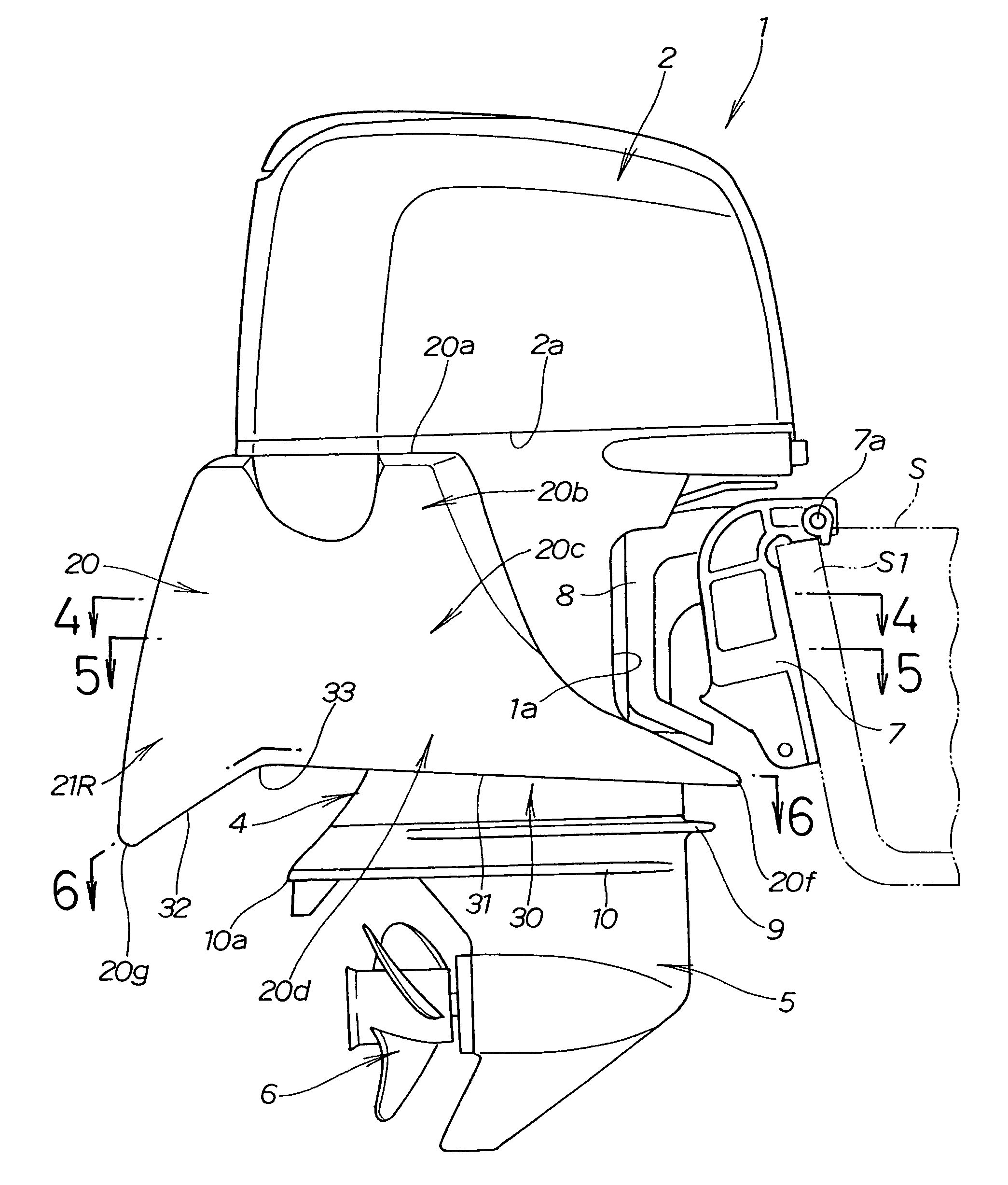
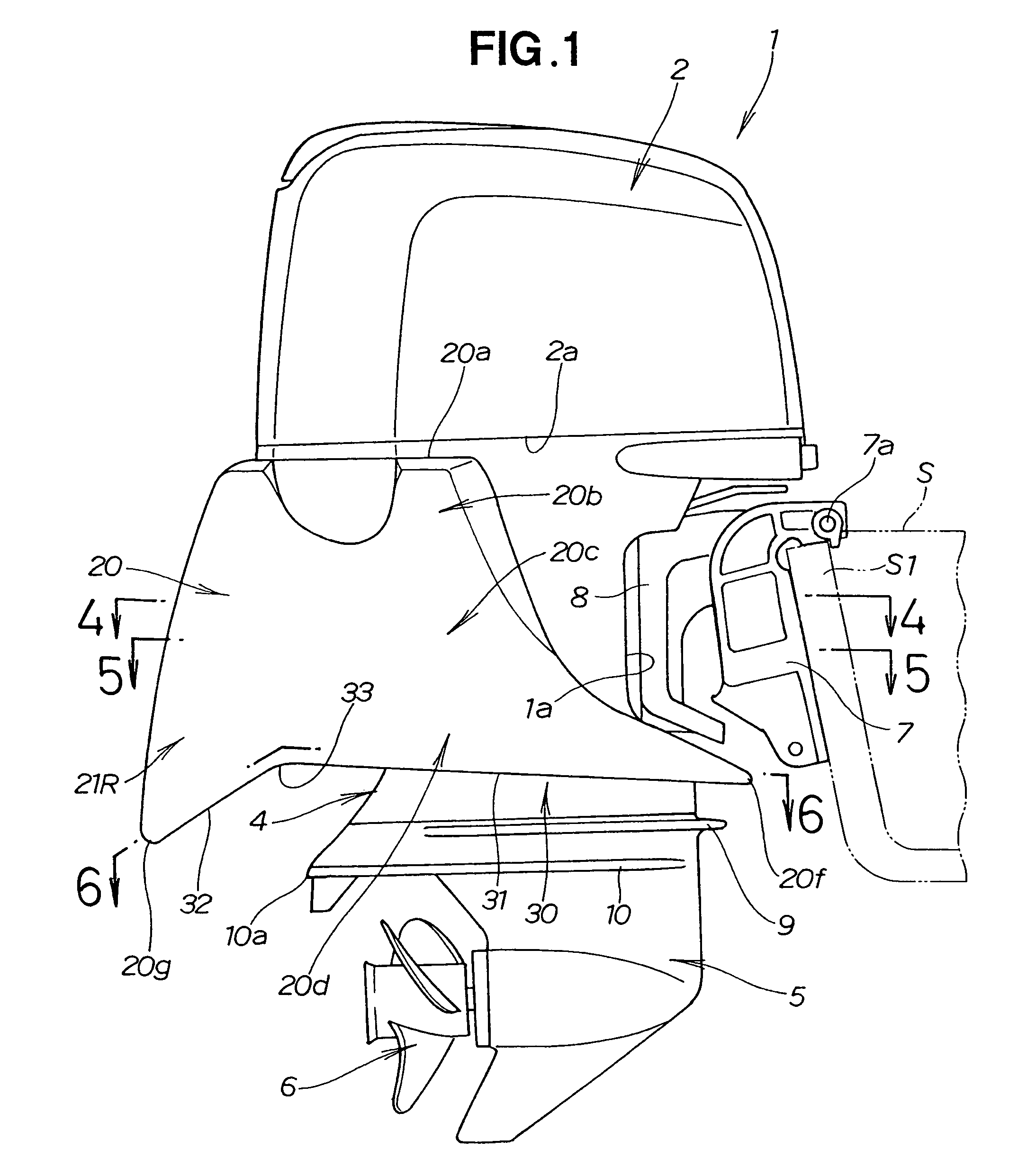
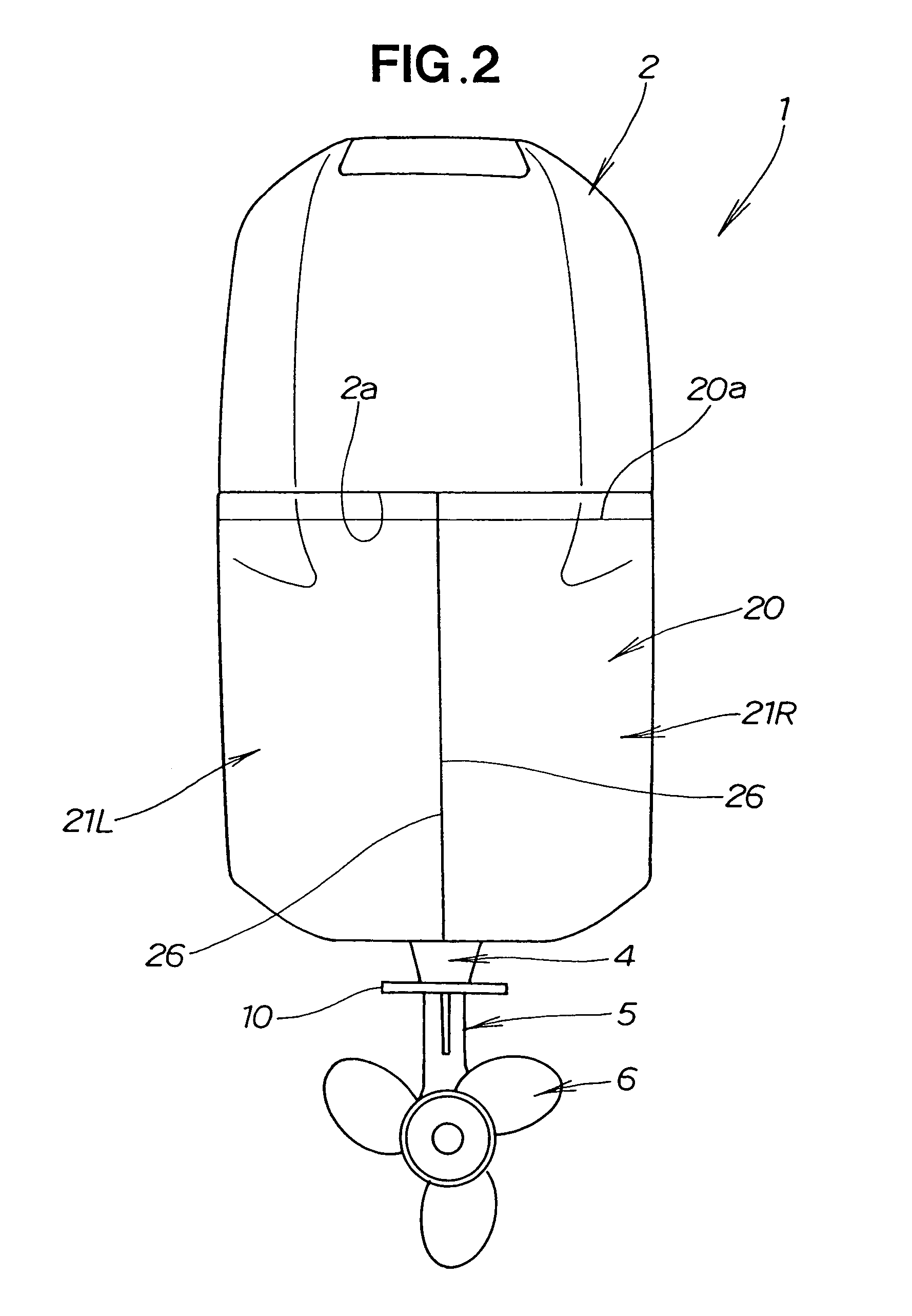
[0037]Referring to FIGS. 1 to 6 inclusive, an outboard engine 1 has an upper engine cover (top cover) 2 that covers the upper portion of an engine (power source) 40, and an undercover 3 that covers the lower portion of the engine 40, as shown in FIGS. 1, 2, and 3. A hollow engine compartment R is formed by and defined between the upper engine cover 2 and undercover 3. An extension case (leg body) 4, which is a drive shaft case, is disposed below the undercover 3. A gear case 5 having a propeller 6 for propulsion is disposed below the extension case 4.

[0038]A concavity 1a that is concave in the rearward direction of the outboard engine 1 is formed on the front portion of the extension case 4. The outboard engine 1 is mounted on the stern S1 of a hull S by way of a stern bracket 7. The stern bracket 7 is mounted on the concavity 1a. A swivel case 8 rotatably supports the outboard engine 1 in the horizontal direction. The outboard engine 1 furthermore swings vertically about a tilt sha...


PUM


Abstract

An outboard engine comprises a power source inside a power source compartment. The power source room is formed by an upper cover and an undercover. A buoyant body is disposed outside the power source compartment, and has a lower surface wall in a position that is lower than the undercover. The buoyant body is provided separately from the upper cover.

Description

CROSS-REFERENCE TO RELATED APPLICATIONS[0001]The present invention claims priority under 35 USC 119 based on Japanese Patent Application No. 2005-240032, filed Aug. 22, 2005, the disclosure of which is incorporated by reference.FIELD OF THE INVENTION[0002]The present invention relates to an outboard engine mounted on the stern of a boat, and more particularly relates to an outboard engine provided with a buoyant body so as to lift the outboard engine upward to allow the boat to move smoothly from a standstill state.BACKGROUND OF THE INVENTION[0003]When a boat that moves by the use of an outboard engine is at a standstill and begins to move, the level of the stern of the boat drops and sinks into the water, and the bow rises and is tilted upward. Since the hull therefore begins to move in a tilted state, the water resistance is considerable when traveling starts, and adequate boat speed cannot be obtained. The stern must rise upward a certain amount, and the orientation of the boat m...

Claims


Application Information

Patent Timeline
Patent Type & Authority Patents(United States)
IPC IPC(8): B63H20/32B63H21/36
CPCB63H20/08B63H20/32Y02T70/10
Inventor SHIOMI, KAZUYUKIIKENO, TETSUROOKADA, TAKESHI
Owner HONDA MOTOR CO LTD
Why Eureka
Try Eureka