Outboard engine

Active Publication Date: 2007-02-22
HONDA MOTOR CO LTD
View PDF3 Cites 0 Cited by
  • Summary
  • Abstract
  • Description
  • Claims
  • Application Information

AI Technical Summary

Benefits of technology

[0025] Thus, the drive shaft case, which houses the exhaust channel, is covered by a noise reduction cover having internal and external walls and an intermediate layer disposed between the walls. The exhaust noise of the engine, machine noise inside the drive sh

Problems solved by technology

Since the hull therefore begins to move in a tilted state, the water resistance is considerable when traveling starts, and adequate boat speed cannot be obtained.
There is a problem in that time is required for the boat to approximate an orientation that is nearly horizontal, and the boat cannot smoothly accelerate.
In the outboard engine of the JP-5-319386A, however, a portion of the lower cowling that forms the engine room is structured to s

Method used


Image

  • Outboard engine
  • Outboard engine
  • Outboard engine

Examples


Embodiment Construction

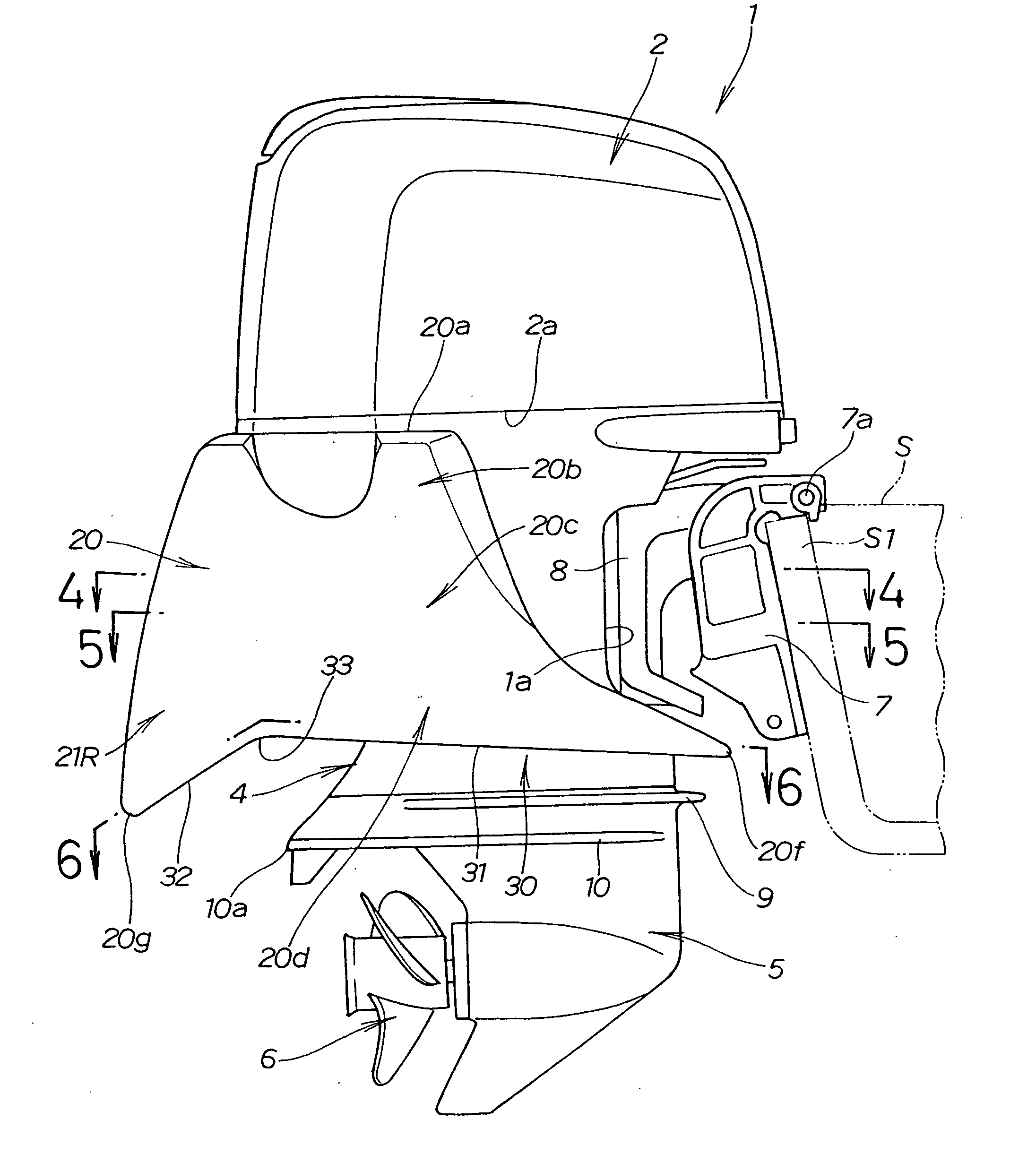
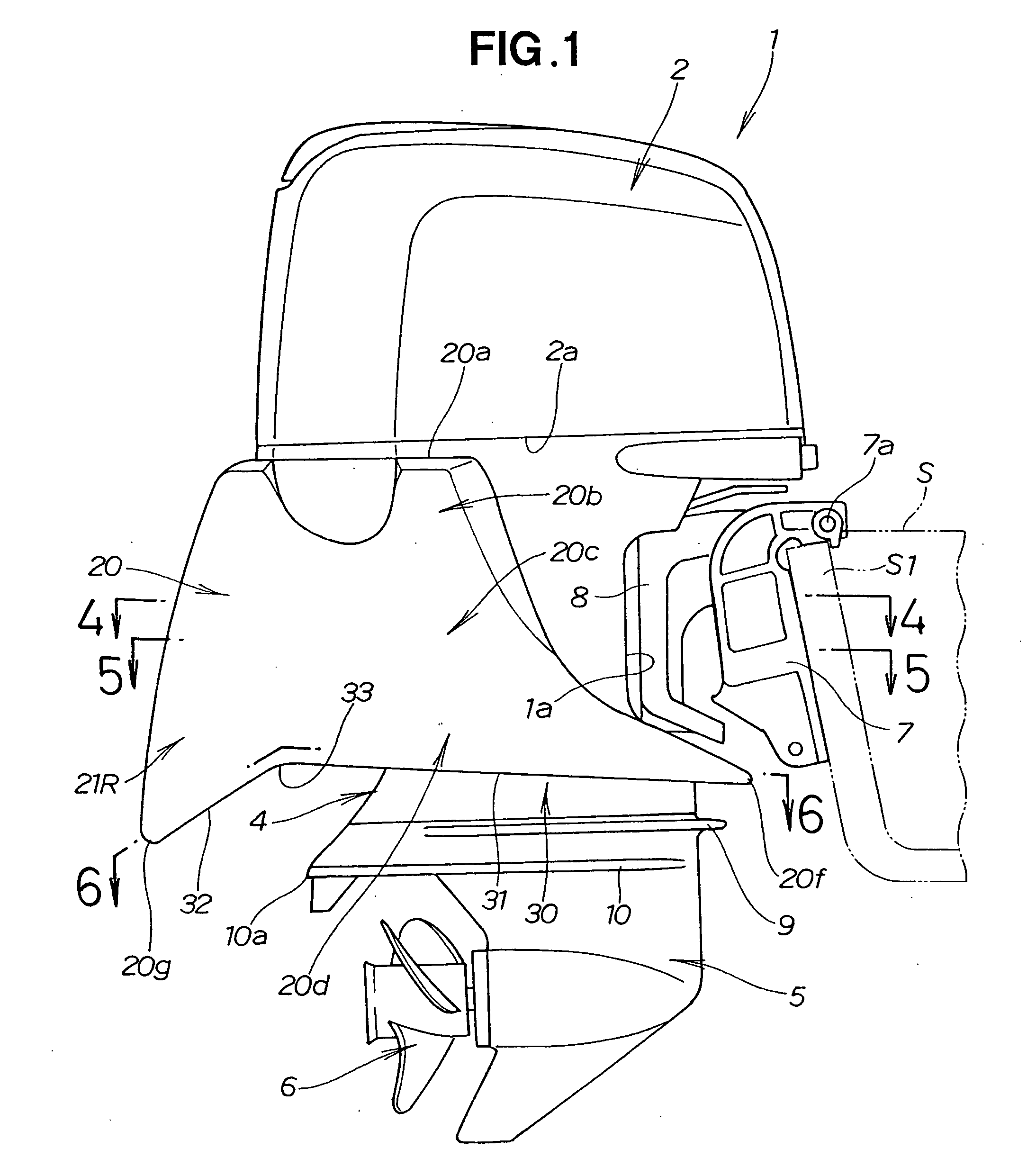
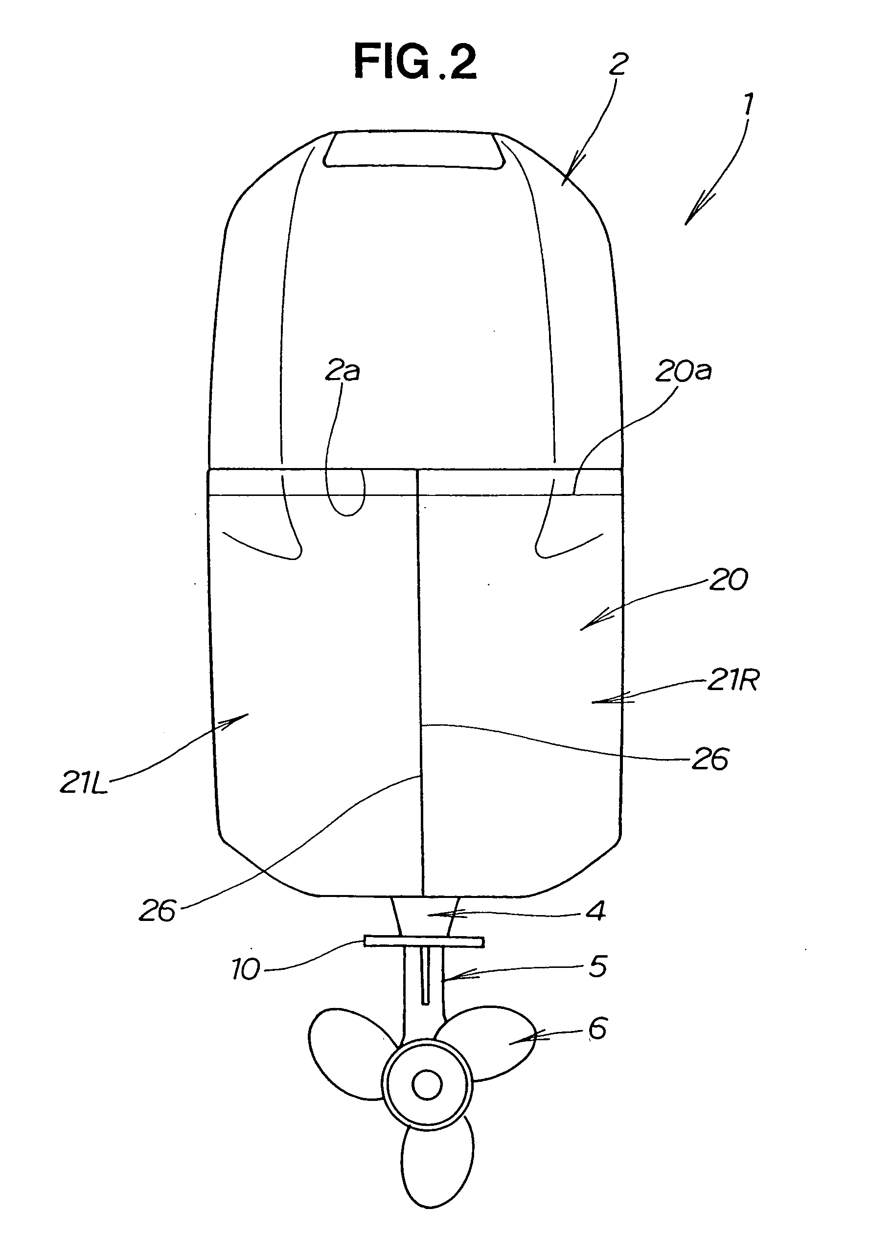
[0036] Referring to FIGS. 1 to 6 inclusive, an outboard engine 1 has a engine cover (top cover) 2 that covers the upper half of an engine (power source) 40, and an undercover 3 that covers the lower half of the engine 40, as shown in FIGS. 1, 2, and 3. An engine room R is formed by the engine cover 2 and undercover 3. An extension case (leg body) 4, which is a drive shaft case, is disposed below the undercover 3. A gear case 5 having a propeller 6 for propulsion is disposed below the extension case 4.

[0037] A concavity 1a that is concave in the rearward direction of the outboard engine 1 is formed on the front portion of the extension case 4. The outboard engine 1 is mounted on the stern S1 of a hull S by way of a stern bracket 7. The stern bracket 7 is mounted on the concavity 1a. A swivel case 8 rotatably supports the outboard engine 1 in the horizontal direction. The outboard engine 1 furthermore swings vertically about a tilt shaft 7a mounted on the stern bracket 7.

[0038] An a...


PUM


Abstract

An outboard engine comprises a power source inside a power source room. The power source room is formed by an upper cover and an undercover. A buoyant body is disposed outside the power source room, and has a lower surface wall in a position that is lower than the undercover. The buoyant body is provided separately from the upper cover.

Description

FILED OF THE INVENTION [0001] The present invention relates to an outboard engine mounted on the stern of a boat, and more particularly relates to an outboard engine provided with a buoyant body so as to lift the outboard engine upward to allow the boat to move smoothly from a standstill state. BACKGROUND OF THE INVENTION [0002] When a boat that moves by the use of an outboard engine is at a standstill and begins to move, the level of the stern of the boat drops and sinks into the water, and the bow rises and is tilted upward. Since the hull therefore begins to move in a tilted state, the water resistance is considerable when traveling starts, and adequate boat speed cannot be obtained. The stern must rise upward a certain amount, and the orientation of the boat must become approximately horizontal in order to reach a certain level of speed. There is a problem in that time is required for the boat to approximate an orientation that is nearly horizontal, and the boat cannot smoothly ...

Claims


Application Information

Patent Timeline
IPC IPC(8): B63H20/32
CPCB63H20/08B63H20/32Y02T70/10
Inventor SHIOMI, KAZUYUKIIKENO, TETSUROOKADA, TAKESHI
Owner HONDA MOTOR CO LTD
Why Eureka
Try Eureka