Load testing device

An experimental device and load technology, applied in the direction of using repetitive force/pulse force to test the strength of materials, etc., can solve problems such as the inability to correct the inclination of the weight 809, the displacement of the center of gravity of the weight 809, and the inability of the weight 809 to be effectively loaded. , to achieve the effect of suppressing the deterioration of test accuracy and easy control

Inactive Publication Date: 2014-01-15
SAGINOMIYA SEISAKUSHO INC
View PDF4 Cites 7 Cited by
  • Summary
  • Abstract
  • Description
  • Claims
  • Application Information

AI Technical Summary

Problems solved by technology

[0008] However, in the above-mentioned floating state, for example, if the horizontal driver 866 moves the vibrating plate 851 in the horizontal direction, the load shaft 826, that is, the weight 809 will be relatively inclined with respect to the base 801. During the control, the inclination of the weight 809 cannot be corrected, and the position of the center of gravity of the weight 809 is shifted. Therefore, the weight 809 cannot be effectively loaded, and there is a concern that the accuracy of the load test may deteriorate.

Method used


Image

  • Load testing device
  • Load testing device
  • Load testing device

Examples


Embodiment Construction

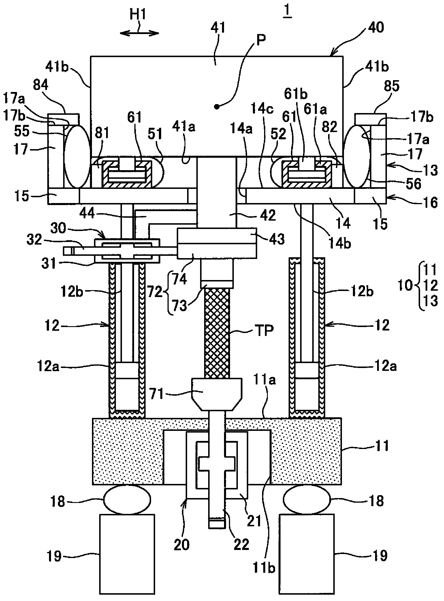
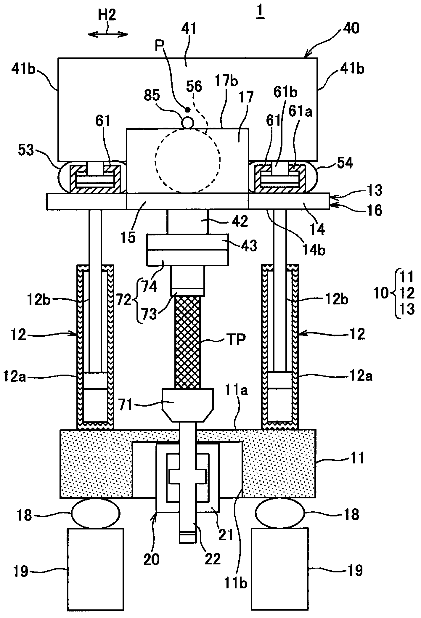
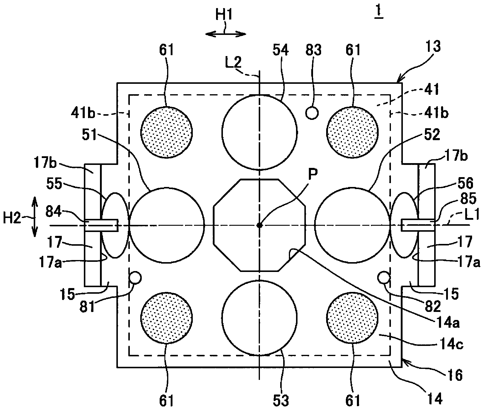
[0039] Next, refer to Figure 1 to Figure 9 , and a load test device according to one embodiment of the present invention will be described.

[0040] The load test apparatus described below is used, for example, to evaluate the dynamic characteristics and static characteristics of a test object by repeatedly applying a compressive or tensile load to a test object such as an engine support cushion rubber of an automobile.

[0041] Figure 1 to Figure 6 In , the structure of the load test device (indicated by symbol 1 in each figure) is shown.

[0042] figure 1 It is a front view of a load test apparatus according to an embodiment of the present invention (a floating state in which a weight can change its position and orientation with respect to a frame). figure 2 yes figure 1 Side view of the load test setup. image 3 yes figure 1 Top view of the loading test setup. Figure 4 yes figure 1 Functional block diagram of the loading test setup. Figure 5 yes figure 1...


PUM

PropertyMeasurementUnit
Resonant frequencyaaaaaaaaaa

Abstract

The invention provides a load testing device which can rectify the inclination of a weight so as to bear the load in the vertical direction of an object to be tested. The load testing device (1) is configured that lower soft bearing components (51-54) are used for supporting from below in a manner that the positional postures of the weight (40) are variable, the upper inclination, caused by a horizontal drive (30) of the weight (40), of a holding part (72) in the moving direction is detected, and based on the detected inclination of the weight (40), the shapes of the lower soft bearing components (51-54) vary in a manner that the posture of the weight (40) is set as a ruled standard posture.

Description

technical field [0001] The present invention relates to a load test device used for a load test in which, for example, a load of compression or tension (in particular, a compressive load) is repeatedly applied to a test object such as an engine support cushion rubber of an automobile, and the test object The dynamic characteristics (especially dynamic spring constant, damping characteristics, etc.) and static characteristics of the body are investigated. Background technique [0002] Patent Document 1 discloses a conventional load test device used for a load test of a test object. like Figure 10 As shown, the load test device has a base 801, a pillar 803 erected on the base 801, a first horizontal head 804 erected between the upper ends of the pillars 803, and a space above the first horizontal head 804. The second horizontal heads 808 arranged at intervals, and the weights 809 arranged at intervals above the second horizontal heads 808 hang down from the center of the sec...

Claims


Application Information

Patent Timeline
Patent Type & Authority Applications(China)
IPC IPC(8): G01N3/34
Inventor 增田洋司古谷桂一
Owner SAGINOMIYA SEISAKUSHO INC
Why Eureka
Try Eureka