Device for installation of a gradient coil unit into a magnetic resonance apparatus

a technology of gradient coil unit and magnetic resonance apparatus, which is applied in the direction of reradiation, magnetic bodies, instruments, etc., can solve the problems of excessive time-consuming and laborious for the implementing technician, and the installation of the gradient coil unit into the magnetic resonance apparatus is not possible without auxiliary means, and achieves the effect of simple manner

Inactive Publication Date: 2007-03-20
SIEMENS AG
View PDF11 Cites 8 Cited by
  • Summary
  • Abstract
  • Description
  • Claims
  • Application Information

AI Technical Summary

Benefits of technology

[0008]An object of the present invention is to provide a device for installation of a gradient coil unit into a magnetic resonance apparatus that allows installation and alignment of the gradient coil unit in a simple manner.
[0009]This object is achieved in accordance with the invention by a device having at least one support unit and at least one carrier unit that is designed to carry the gradient coil unit and on which the at least one support unit is carried such that it can be tilted via a connector. The support unit is brought into the receptacle (tunnel) of the magnetic resonance apparatus with the gradient coil unit and is aligned. In the installation of the gradient coil unit, it is positioned such that its magnetic center is in or at the magnetic center of the basic field magnet. By the use of a tiltable connector, it is possible in a simple manner to correct the tilt of the gradient coil unit with regard to its axis of symmetry. This avoids the conventional protracted adjustment event with shims within the basic field magnet.
[0010]In an embodiment, the at least one carrier unit can be tilted relative to an axis that is parallel to a longitudinal axis of the support unit. This enables a simple alignment of the gradient coil unit with regard to this longitudinal axis. This adjustment event is particularly important for a gradient coil unit built in a cylindrical shape, as is common.
[0011]One possibility for correcting a non-ideally-aligned gradient coil unit is the use of weight elements that are mounted on the carrier unit such that they can be moved and secured. By moving the weight elements the technician can effect an optimization of the angle position of the gradient coil unit in a simple manner.
[0013]The at least one support unit has a support segment with a support surface (contact surface) for movable support of the connector. For example, the position of the gradient coil unit can be optimized in a simple manner within the basic field magnet, and the magnetic center of the gradient coil unit thus can be positioned in the magnetic center of the basic field magnet.
[0014]In a preferred embodiment of the invention, the connector exhibits a tapering at both ends with regard to an axis lying perpendicular to the cross-section. The support surface is planar. Due to the use of barrel-shaped roller, the gradient coil unit (connected, for example, with the carrier unit) automatically aligns within the basic field magnet by gravity. The gradient coil unit thus can be tilted on its axis of symmetry in a limited range, such that the correct (with regard to the angle) position can be adjusted in a simple manner. In this manner, only a little work still needs to be conducted for the alignment of the gradient coil unit. In particular iterative alignments by means of shims is avoided.

Problems solved by technology

The mass of a gradient coil unit of a magnetic resonance apparatus is generally more than 100 kilograms, such that installation thereof into the magnetic resonance apparatus is not possible without auxiliary means.
The described procedure is exceedingly time-consuming and laborious for the implementing technician.

Method used


Image

  • Device for installation of a gradient coil unit into a magnetic resonance apparatus
  • Device for installation of a gradient coil unit into a magnetic resonance apparatus
  • Device for installation of a gradient coil unit into a magnetic resonance apparatus

Examples


Embodiment Construction

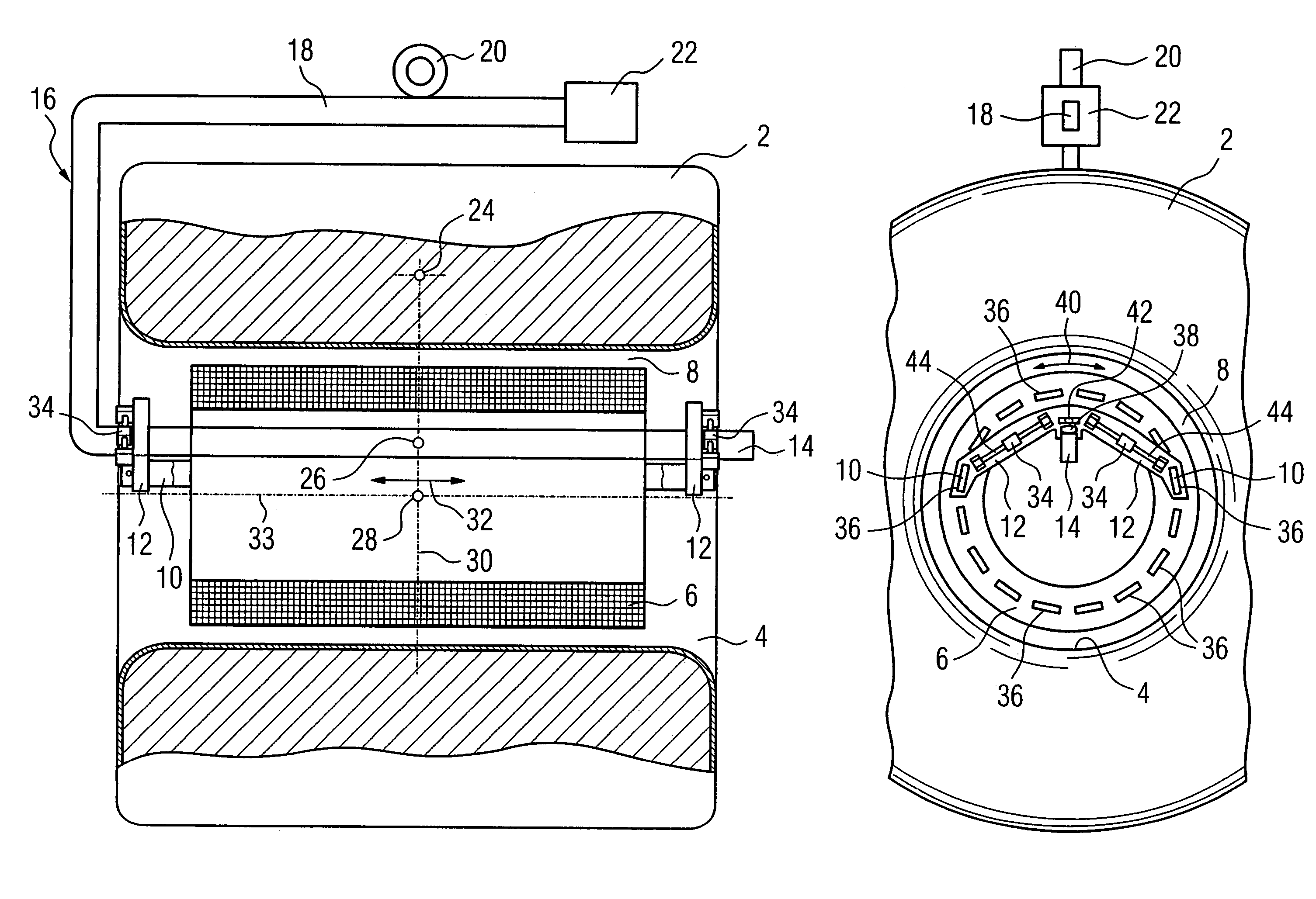
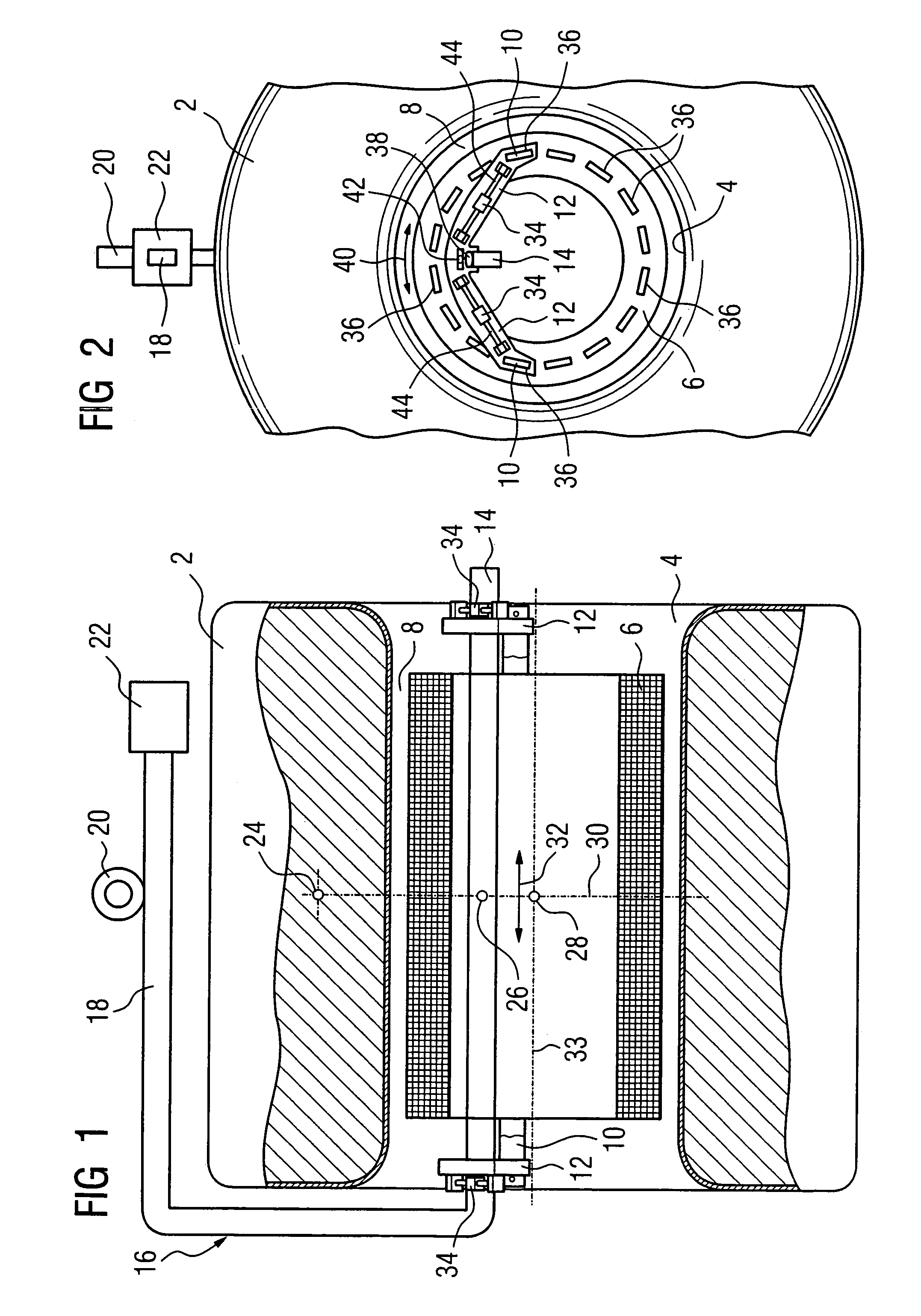
[0019]As shown in FIG. 1, a magnetic resonance apparatus has a basic field magnet 2 with a tubular longitudinal opening 4. A gradient coil unit 6 is installed into the opening 4. For a better overview, the resulting gap 8 between the gradient coil unit 6 and the basic field magnet 2 is shown over-proportionally large in comparison with the size of the basic field magnet 2. The gradient coil unit 6 is connected via metal carriers 10 with two carrier units 12 that are supported on a support bar or rail 14 such that they can move along it. The support bar 14 traverses the gradient coil unit 6 and is larger in terms of length than the basic field magnet 2. The support bar 14 is part of a C-shaped support unit 16. The support unit 16 has a load arm 18 with an annular receptacle (eye) 20 for attachment to a crane (not shown here). A counterweight 22 that serves for compensation of the asymmetrical (due to the C-shape) weight distribution of the support unit 16 is attached on the load arm ...


PUM

PropertyMeasurementUnit
massaaaaaaaaaa
weightaaaaaaaaaa
diameteraaaaaaaaaa

Abstract

A device for installation of a gradient coil unit into a magnetic resonance apparatus has at least one support unit and at least one carrier unit. The carrier unit is fashioned to carry the gradient coil unit, and the at least one support unit is supported thereon such that it can tilt on a connector.

Description

BACKGROUND OF THE INVENTION[0001]1. Field of the Invention[0002]The present invention concerns a device for installation of a gradient coil unit into a magnetic resonance apparatus.[0003]2. Description of the Prior Art[0004]For the installation of heavier components of a medical apparatus, an auxiliary device is frequently required that assists the technician. The mass of a gradient coil unit of a magnetic resonance apparatus is generally more than 100 kilograms, such that installation thereof into the magnetic resonance apparatus is not possible without auxiliary means. In magnetic resonance apparatuses, the gradient coil unit is supported (mounted) within a basic field magnet. A gap thus exists between the basic field magnet and the gradient coil unit. This gap is only a few millimeters, while the diameter of the receptacle (retainer) for the gradient coil unit is several hundreds of millimeters. It is therefore necessary to exactly position the gradient coil unit. In particular t...

Claims


Application Information

Patent Timeline
Patent Type & Authority Patents(United States)
IPC IPC(8): G01R33/385
CPCG01R33/3858Y10T29/49073Y10T29/4902Y10T29/53974Y10T29/53961Y10T29/53261Y10T29/53265Y10T29/5313
Inventor SCHUSTER, JOHANNSTOCKER, STEFAN
Owner SIEMENS AG
Why Eureka
Try Eureka