
Imaging device

a technology of a camera and an insertable optical element, which is applied in the field of imaging devices, can solve the problems of increasing the production cost of the device and the size of the device which includes these cameras, and achieves the effect of small movement of the insertable optical elemen

Inactive Publication Date: 2012-01-17
HOYA CORP
View PDF12 Cites 3 Cited by
  • Summary
  • Abstract
  • Description
  • Claims
  • Application Information

AI Technical Summary

Benefits of technology

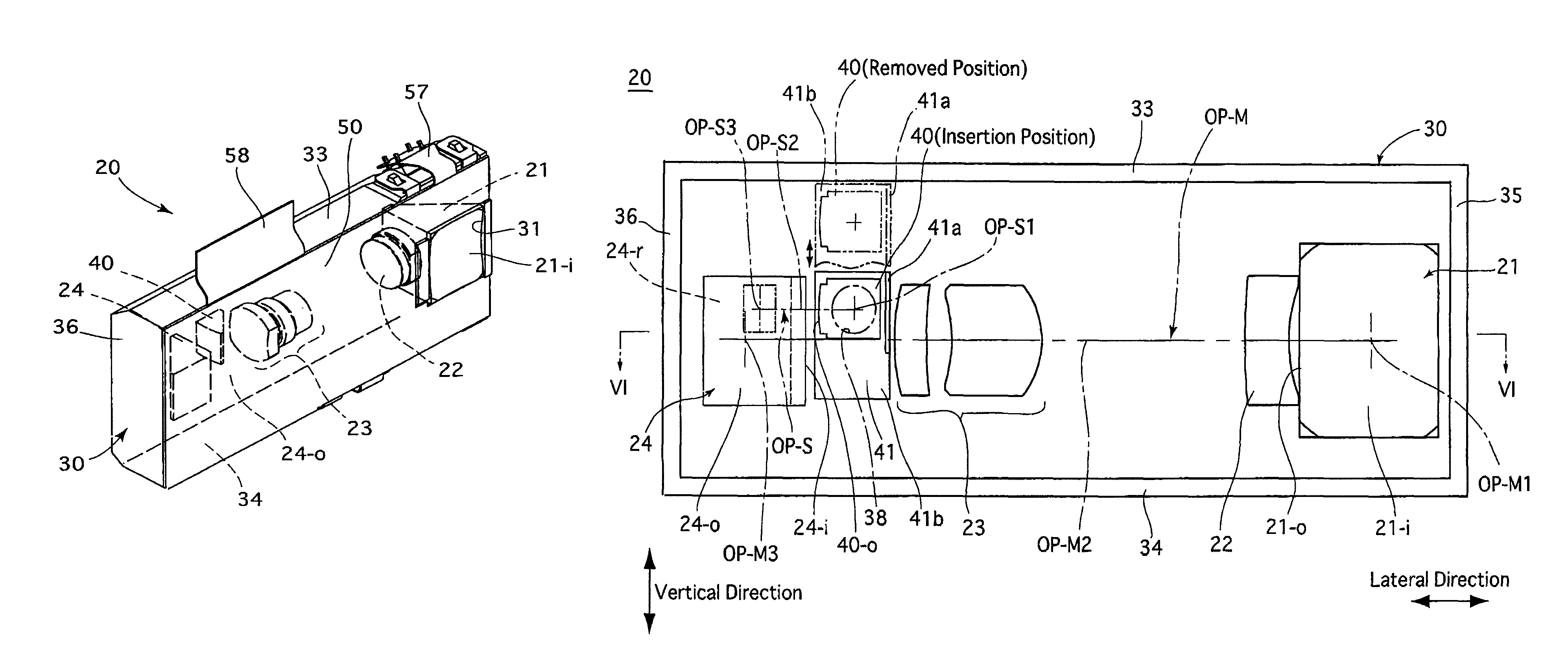
The present invention provides an imaging device that can capture images of objects at opposite locations and can be made smaller in size than conventional imaging devices. The device includes a housing with two photographing apertures, an image pickup device, a main optical system, and an insertable optical element which can be moved between an insertion position and a removed position. The insertable optical element can be a prism or a light-shielding plate. The device can be used for high-pixel-resolution or low-pixel-resolution photographing operations depending on the position of the insertable optical element. The device can be incorporated in a mobile electronic device with cameras facing outward and inward windows, respectively. The invention allows for small imaging devices with a switch between different imaging directions and minimal movement of the insertable optical element.

Problems solved by technology

If two separate imaging units are provided as the inward-facing camera and the outward-facing camera, respectively, the device which includes these cameras increases in size and the production cost of the device also increases.

Method used


Image

  • Imaging device
  • Imaging device
  • Imaging device

Examples


Embodiment Construction

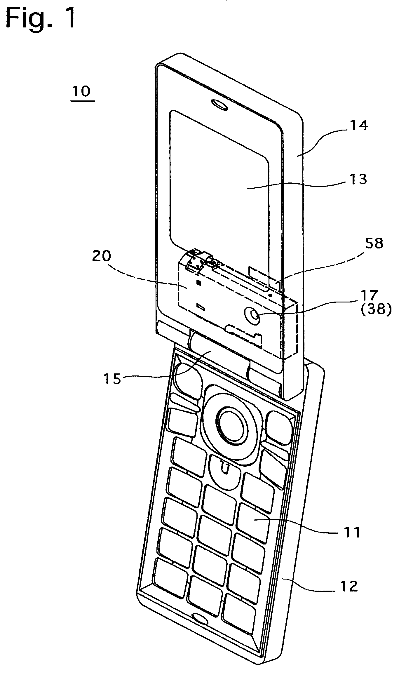
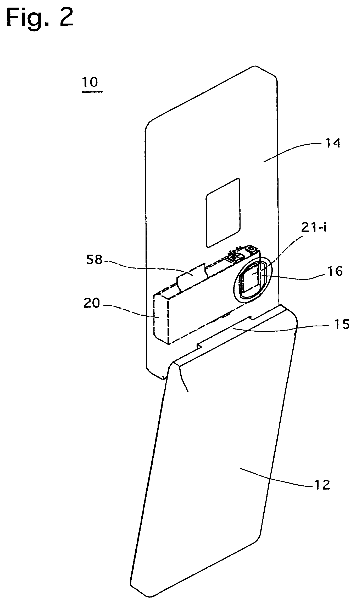
[0036]A mobile phone (cellular phone) 10 shown in FIGS. 1 and 2 which is equipped with an outward-facing camera (main camera) and an inward-facing camera (sub-camera) is a folding type which is provided with a foldable housing including an operational portion 12 and a display portion 14, and is further provided between the operational portion 12 and the display portion 14 with a hinge 15. The operational portion 12 and the display portion 14 are hingedly connected with each other via the hinge 15 to be allowed to rotate relative to each other about the axis of the hinge 15 so that the mobile phone 10 can change between an operating state (fully open state / unfolded state) shown in FIGS. 1 and 2, in which the operational portion 12 and the display portion 14 are fully opened, and a folded state (not shown) in which the mobile phone 10 is folded so that the operational portion 12 and the display portion 14 overlay each other. The operational portion 12 is provided with a plurality of o...


PUM


Abstract

An imaging device includes a housing including first and second photographing apertures which are open toward opposite directions; an image pickup device provided in the housing; a main optical system forming incident light from the first photographing aperture onto an imaging surface of the image pickup device; and an insertable optical element movable between an insertion position in an optical path of a main optical system and a removed position out of the optical path of the main optical system, the insertable optical element constituting at least a part of a sub-optical system which forms incident light from the second photographing aperture onto the imaging surface when at the insertion position. When the insertable optical element is positioned in the insertion position, the sub-optical axis is offset from the main optical axis toward the removed position of the insertable optical element in the inserting / removing direction.

Description

BACKGROUND OF THE INVENTION[0001]1. Field of the Invention[0002]The present invention relates to an imaging device, more specifically to an imaging device incorporated in a mobile electronic device such as a mobile phone.[0003]2. Description of the Related Art[0004]In recent years, mobile electronic devices such as mobile phones with an inward-facing camera (sub-camera) in addition to an outward-facing camera (main camera) have been in widespread use. The outward-facing camera is used to capture still images or video clips of ordinary subjects while the inward-facing camera is used to capture still images or video clips of the user himself / herself for, e.g., video conferencing. If two separate imaging units are provided as the inward-facing camera and the outward-facing camera, respectively, the device which includes these cameras increases in size and the production cost of the device also increases. Accordingly, it has been desired to provide an imaging device which is equipped wi...

Claims


Application Information

Patent Timeline
Patent Type & Authority Patents(United States)
IPC IPC(8): H04N5/225
CPCH04N5/2252H04N5/2257H04N23/57H04N23/51
Inventor NOMURA, HIROSHIKANEKO, ATSUMIOKUDA, ISAOTADA, EIJIROH
Owner HOYA CORP
Learn More