Vehicle brake pedal device

a brake pedal and vehicle technology, applied in mechanical control devices, process and machine control, instruments, etc., can solve the problems of inability to mount the brake pedal device on this type of vehicle, the pushrod is difficult to bend by the rotation arm, etc., to reduce the fear of breaking load, suppress the backward movement of the brake pedal pad, and reduce the effect of breaking load

Active Publication Date: 2017-11-21
TOYOTA JIDOSHA KK
View PDF13 Cites 3 Cited by
  • Summary
  • Abstract
  • Description
  • Claims
  • Application Information

AI Technical Summary

Benefits of technology

[0012]The present invention has been made in view of the above-mentioned problem, and therefore has an object to provide a vehicle brake pedal device, which is capable of making a backward movement amount of a brake pedal pad small when a partition wall configured to support a pedal bracket is deformed backward, and is mountable also on a vehicle having a short push rod (such as a minivan).

Problems solved by technology

However, in a small vehicle (such as a minivan), a fore-and-aft length of the pushrod is small, thereby being difficult to bend the pushrod by the rotation arm.
In other words, this brake pedal device cannot be mounted on this type of vehicle.

Method used


Image

  • Vehicle brake pedal device
  • Vehicle brake pedal device
  • Vehicle brake pedal device

Examples


first embodiment

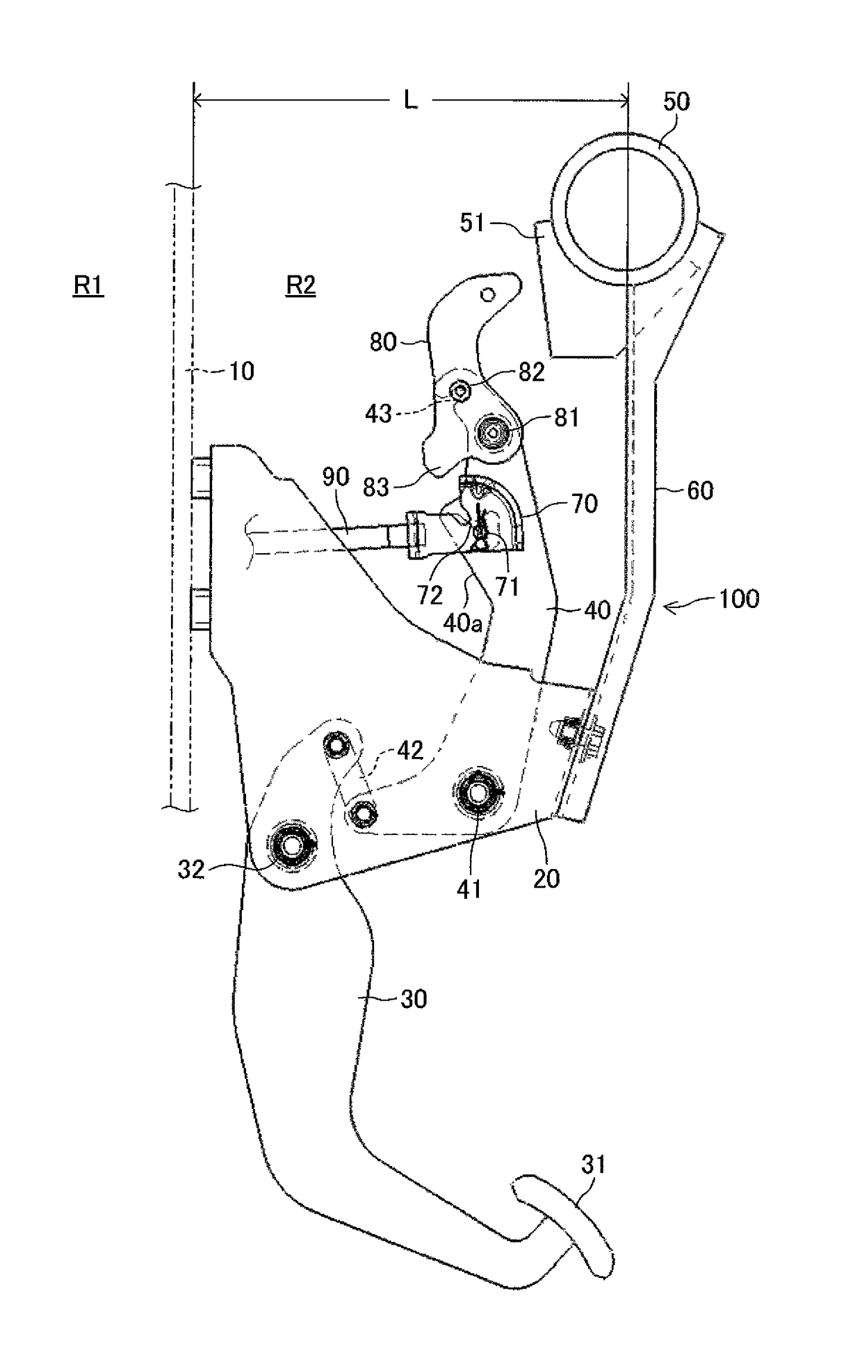
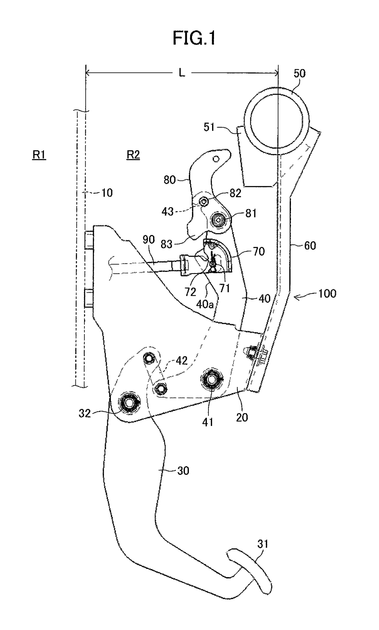
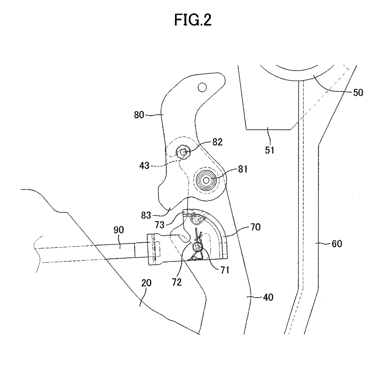
[0066]The clevis 110 is coupled to the coupling arm 40 and the pushrod 90 in the same manner as that of the In other words, the rear end vicinity part of the push rod 90 is inserted into and fixed to (fasten to) the mounting hole 110a1 of the base part 110A of the clevis 110. Further, both left and right ends of the coupling pin 71 are respectively inserted into the left and right insertion round holes 110b1 and 110c1 of the clevis 110. The outer diameter of the coupling pin 71 is slightly smaller than (in other words, approximately equal to) diameters of the insertion round holes 110b1 and 110c1, and is apparently larger than widths of the guide grooves 110b2 and 110c2.

[0067]In the vehicle brake pedal device 200, in the normal state (in the state before the vehicle having the vehicle brake pedal device 200 mounted thereon collides with another vehicle or the like), the respective components are in a state illustrated in FIG. 10. Therefore, when the forward and obliquely downward d...

second embodiment

[0086]As a matter of course, the depression force switch S may be applied to the vehicle brake pedal device 200 according to the


PUM


Abstract

The vehicle brake pedal device includes a pedal bracket fixed to a partition wall, a brake arm and a coupling arm assembled to the pedal bracket, a clevis and a movable plate assembled to the coupling arm, and a fixed member and a coupling bracket assembled to a vehicle body component. In the event of a front collision of the vehicle, the pedal bracket is moved backward, and the movable plate is brought into abutment against the fixed member to rotate. As a result, a push part of the movable plate is brought into abutment against the clevis, and a breakable part of the clevis is broken so that the clevis and the coupling arm are decoupled from each other. Then, the coupling arm is rotated forward with respect to the pedal bracket.

Description

BACKGROUND OF THE INVENTION[0001]1. Field of the Invention[0002]The present invention relates to a vehicle brake pedal device, and more particularly, to a vehicle brake pedal device configured to suppress a backward movement of a brake pedal when a partition wall (dash panel) is moved inside a vehicle cabin as a result of a front collision of a vehicle.[0003]2. Description of the Related Art[0004]The vehicle brake pedal device of this type is described, for example, in Japanese Patent Application Laid-open No. 2014-40201. In the vehicle brake pedal device described in Japanese Patent Application Laid-open No. 2014-40201, a brake pedal device including a brake arm with a brake pedal pad is arranged on a vehicle cabin side of (behind) a dash panel, which is a partition wall, and a braking hydraulic pressure generation device including a brake booster and a master cylinder is arranged in front of the dash panel. Further, a link mechanism linked to the brake arm and the braking hydrauli...

Claims


Application Information

Patent Timeline
Patent Type & Authority Patents(United States)
IPC IPC(8): B60T7/06G05G1/327G05G1/323G05G1/30
CPCB60T7/065G05G1/327G05G1/323G05G1/30
Inventor UCHIDA, SATOSHIYASUE, SATOSHIAOKI, SHINICHIRO
Owner TOYOTA JIDOSHA KK
Why Eureka
Try Eureka