Drive mechanism for articulation of a surgical instrument

a surgical instrument and drive mechanism technology, applied in the field of surgical instrument drive mechanism, can solve the problems of bulky or unwieldy mechanisms that permit this articulation function

Active Publication Date: 2013-03-26
TYCO HEALTHCARE GRP LP
View PDF21 Cites 996 Cited by
  • Summary
  • Abstract
  • Description
  • Claims
  • Application Information

AI Technical Summary

Problems solved by technology

Mechanisms that permit this articulation functionality are often bulky or unwieldy, particularly when the mechanisms to perform the other procedures are also incorporated into a single surgical instrument.

Method used


Image

  • Drive mechanism for articulation of a surgical instrument
  • Drive mechanism for articulation of a surgical instrument
  • Drive mechanism for articulation of a surgical instrument

Examples


Embodiment Construction

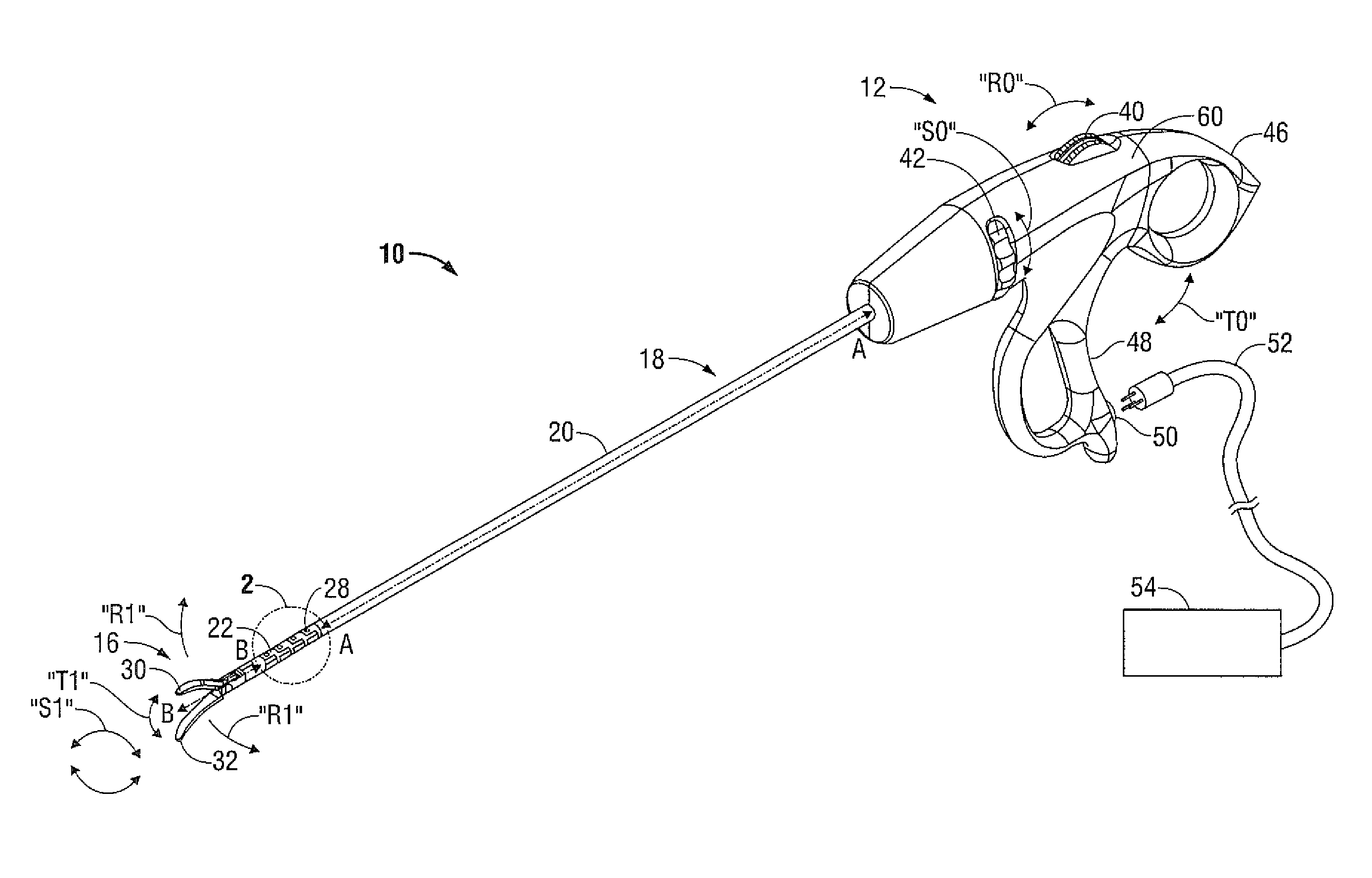
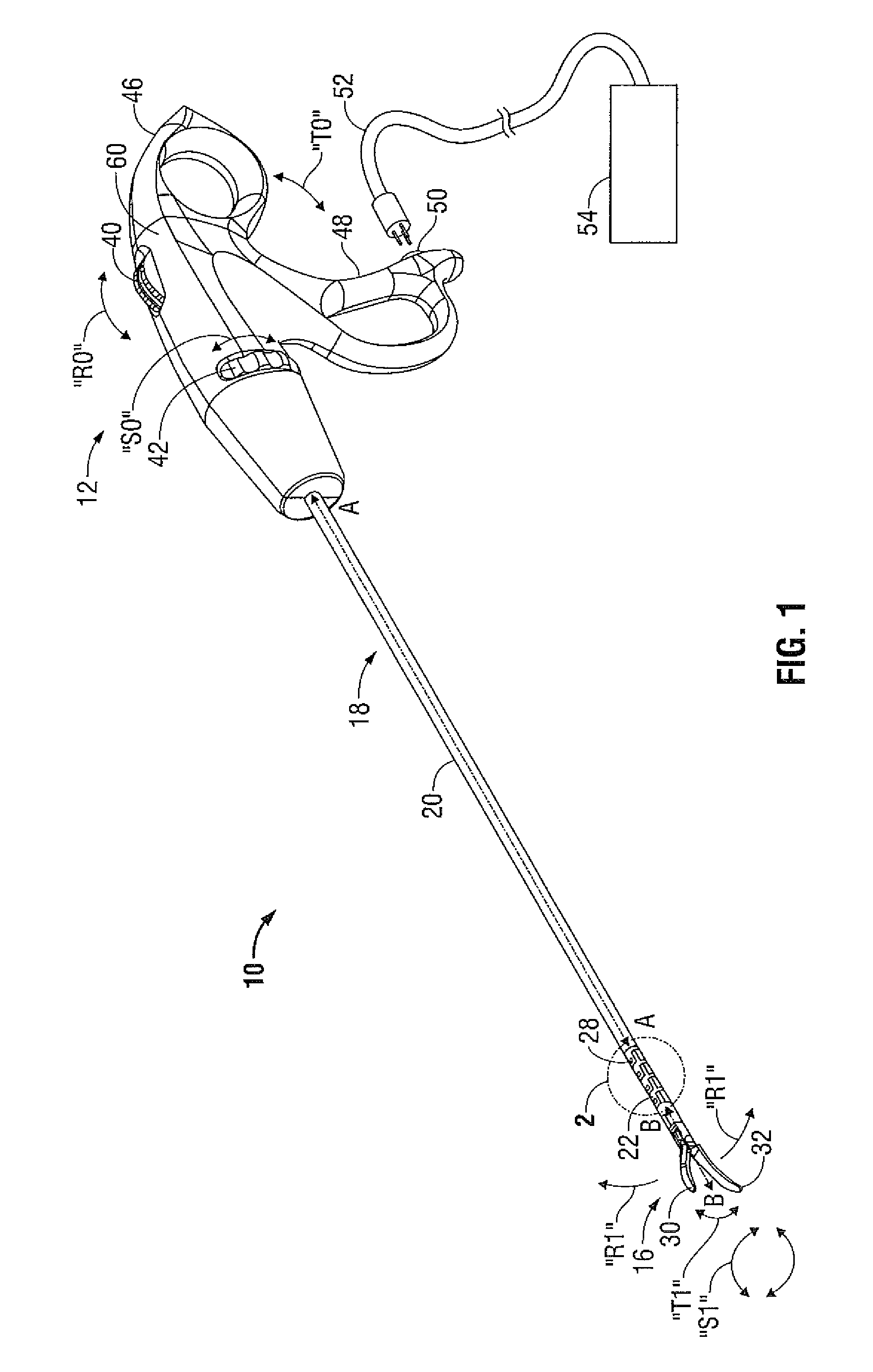
[0021]Referring initially to FIG. 1, an embodiment of an electrosurgical instrument is depicted generally as 10. The instrument 10 includes a housing 12 remotely supporting an end effector 16 through an elongated shaft 18. Although this configuration is typically associated with instruments for use in endoscopic surgical procedures, various aspects of the present disclosure may be practiced in connection with traditional open procedures as well.

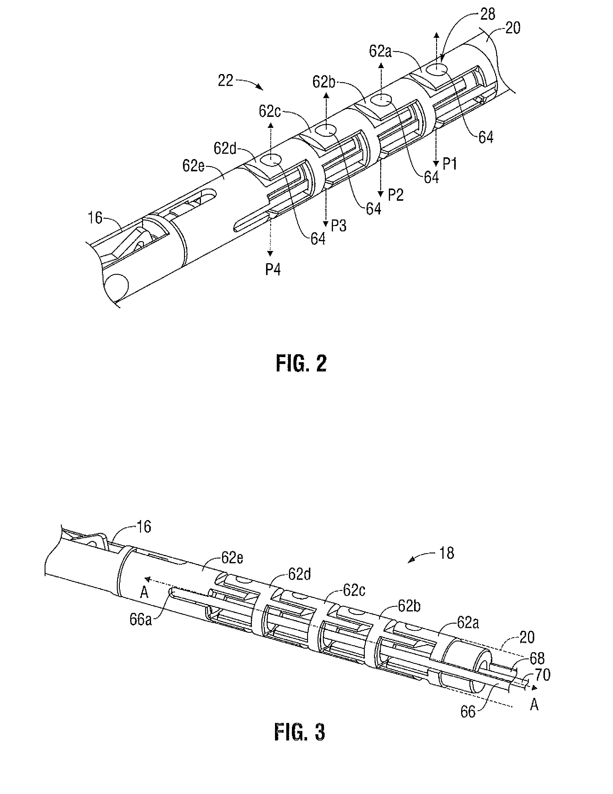
[0022]Elongated shaft 18 includes a proximal portion 20 extending from the housing 12 and an articulating distal portion 22 supporting the end effector 16. The proximal portion 20 defines a longitudinal axis A-A, and is sufficiently long to position the end effector 16 through a cannula (not shown). The articulating distal portion 22 defines at least one joint 28 between the proximal portion 20 of the elongated shaft 18 and the end effector 16 permitting the end effector 16 to articulate or pivot relative to the longitudinal axis A-A. The end...


PUM


Abstract

A surgical instrument includes a housing, an end effector and an elongated shaft extending therebetween. The shaft includes a distal portion movable between aligned and articulated configurations. First and second drive cables are coupled to the distal portion such that reciprocal longitudinal motion of the drive cables induces movement of the distal portion between the aligned and articulated configurations. An articulation drive mechanism is operable to induce reciprocal longitudinal motion of the drive cables. The drive mechanism includes an actuator and a pair pulleys operatively coupled to the actuator to rotate about an axle. The first and second drive cables are coupled to the pulleys such that the drive cables extend on opposite lateral sides of the axle. A biasing mechanism is configured to bias the first and second pulleys to at least one discrete orientation to maintain the distal portion of the elongated shaft in a discrete articulated position.

Description

BACKGROUND[0001]1. Technical Field[0002]The present disclosure relates to an apparatus for surgically treating tissue. In particular, the disclosure relates to a mechanism for orienting a distal portion of the instrument by manipulating an actuator at a proximal end of the instrument.[0003]2. Background of Related Art[0004]Instruments such as electrosurgical forceps are commonly used in open and endoscopic surgical procedures to coagulate, cauterize and seal tissue. Such forceps typically include a pair of jaws that can be controlled by a surgeon to grasp targeted tissue, such as, e.g., a blood vessel. The jaws may be approximated to apply a mechanical clamping force to the tissue, and are associated with at least one electrode to permit the delivery of electrosurgical energy to the tissue. The combination of the mechanical clamping force and the electrosurgical energy has been demonstrated to join adjacent layers of tissue captured between the jaws. When the adjacent layers of tiss...

Claims


Application Information

Patent Timeline
Patent Type & Authority Patents(United States)
IPC IPC(8): A61B17/29A61B18/14
CPCA61B18/1445A61B2017/00314A61B2017/00327A61B2017/2908A61B2017/2923A61B2017/2927A61B2018/1432A61B2017/003
Inventor CUNNINGHAM, JAMES S.CARLSON, RICHARDSPINALI, MARC
Owner TYCO HEALTHCARE GRP LP
Why Eureka
Try Eureka