Card connector

a card connector and card slot technology, applied in the direction of coupling device connection, coupling/disconnecting parts, instruments, etc., can solve the problem of inconvenient us

Inactive Publication Date: 2013-04-16
CHENG UEI PRECISION IND CO LTD
View PDF11 Cites 22 Cited by
  • Summary
  • Abstract
  • Description
  • Claims
  • Application Information

AI Technical Summary

Benefits of technology

[0008]As described above, the tray pushes the pushing body rearward to drive the sliding block rearward or forward under a cooperation of the guide pin and the elastic element to make the buckling portion buckled in the buckling groove or apart from the buckling groove so as to lock the tray together with the micro-SIM card in the receiving space of the card connector or eject the tray together with the micro-SIM card out of the card connector effectively.

Problems solved by technology

However, the tray together with the micro-SIM card inserted into the insertion space of the card connector is often apt to slide off from the card connector to suddenly interrupt the contact of the micro-SIM card and the contact portions of the terminals.
Moreover, the above-mentioned card connector has no ejection mechanism that brings inconvenience for users to eject the tray together with the micro-SIM card out of the card connector.

Method used


Image

  • Card connector
  • Card connector
  • Card connector

Examples


Embodiment Construction

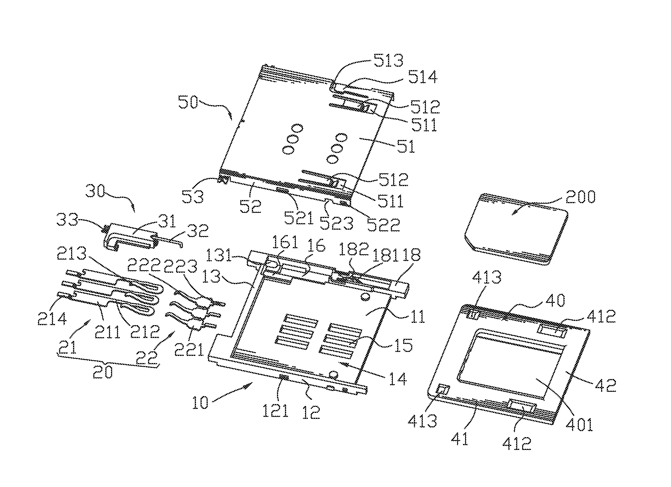
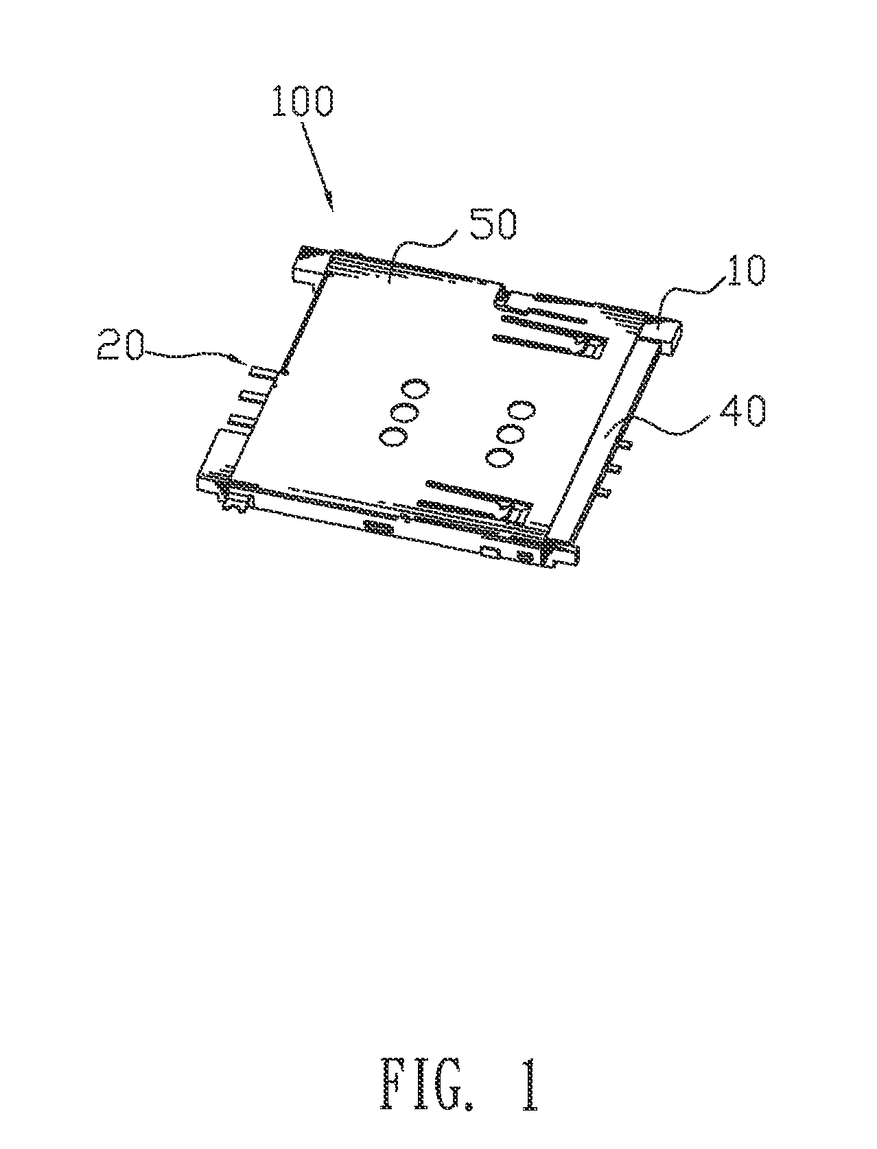
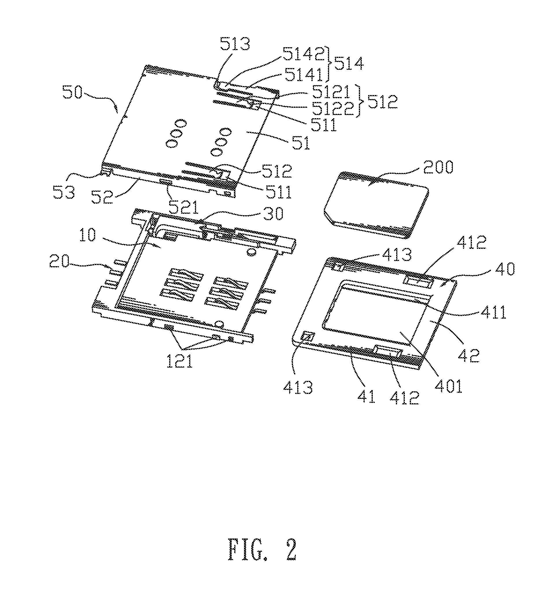
[0016]With reference to FIGS. 1-3, a card connector 100 in accordance with the present invention is shown. The card connector 100 adapted for receiving a micro-SIM card 200 therein includes an insulating housing 10, a plurality of terminals 20, an ejection mechanism 30, a tray 40 and a shielding shell 50.

[0017]Referring to FIGS. 2-3, the insulating housing 10 has a base board 11 of a rectangular shape. Two opposite sides of the base board 11 extend upward to form two side walls 12. A rear end of the base board 11 extends upward to form a rear wall 13 connecting between the two side walls 12. A receiving space 14 is formed among the base board 11, the two side walls 12 and the rear wall 13. The base board 11 defines two rows of rectangular openings 15 located at a front thereof and at a rear thereof, respectively. Each row of the openings 15 are arranged at regular intervals along a transverse direction. Each of the openings 15 vertically penetrates through the base board 11. One sid...


PUM


Abstract

A card connector adapted for receiving a micro-SIM card therein includes an insulating housing, a plurality of terminals disposed in the insulating housing, a tray and a shielding shell covered on the insulating housing. The ejection mechanism includes a sliding block having a pushing body, a guide pin and an elastic element. A top of the tray defines at least one buckling groove. A top of the shielding shell defines at least one limiting tab having a buckling portion. The tray pushes the pushing body to drive the sliding block rearward or forward under a cooperation of the guide pin and the elastic element to make the buckling portion buckled in the buckling groove or apart from the buckling groove so as to lock the tray together with the micro-SIM card in the card connector or eject the tray together with the micro-SIM card out of the card connector.

Description

BACKGROUND OF THE INVENTION[0001]1. Field of the Invention[0002]The present invention generally relates to a card connector, and more particularly to a card connector capable of locking a micro-SIM card therein and ejecting the micro-SIM card out therefrom effectively.[0003]2. The Related Art[0004]Generally, a conventional card connector adapted for receiving a micro-SIM (micro-Subscriber Identification Module) card therein is widely used in electronic communication devices, such as cell phones. The card connector is soldered on a circuit board of the electronic communication device to communicate between the micro-SIM card and the circuit board so as to realize data identification.[0005]The card connector includes an insulating housing, a plurality of terminals, a tray and a shielding shell. The insulating housing defines a plurality of terminal grooves vertically penetrating therethrough and extending longitudinally to pass through one end of the insulating housing. Each of the te...

Claims


Application Information

Patent Timeline
Patent Type & Authority Patents(United States)
IPC IPC(8): H01R13/635
CPCG06K7/0021G06K13/0825G06K13/0831G06K13/085
Inventor JI, MEI-LICHANG, JUI-MINGLIU, ZHU-RUI
Owner CHENG UEI PRECISION IND CO LTD
Why Eureka
Try Eureka