Image forming apparatus

a technology of image forming apparatus and intermediate transfer belt, which is applied in the direction of electrographic process apparatus, instruments, optics, etc., can solve the problems of preventing correct image quality adjustment, unstable image formation, and the inability to reduce the friction of the intermediate transfer belt to a valu

Inactive Publication Date: 2013-04-16
RICOH KK
View PDF26 Cites 6 Cited by
  • Summary
  • Abstract
  • Description
  • Claims
  • Application Information

AI Technical Summary

Problems solved by technology

However, because the photosensitive elements are always coated with the lubricant and because the lubricant is transferred from the intermediate transfer belt to the recording sheet and the belt member, the coefficient of friction of the intermediate transfer belt cannot decrease to a value lower than the coefficient of friction of the photosensitive elements.
This prevents correct image quality adjustment and leads to unstable image formation.

Method used


Image

  • Image forming apparatus
  • Image forming apparatus
  • Image forming apparatus

Examples


first embodiment

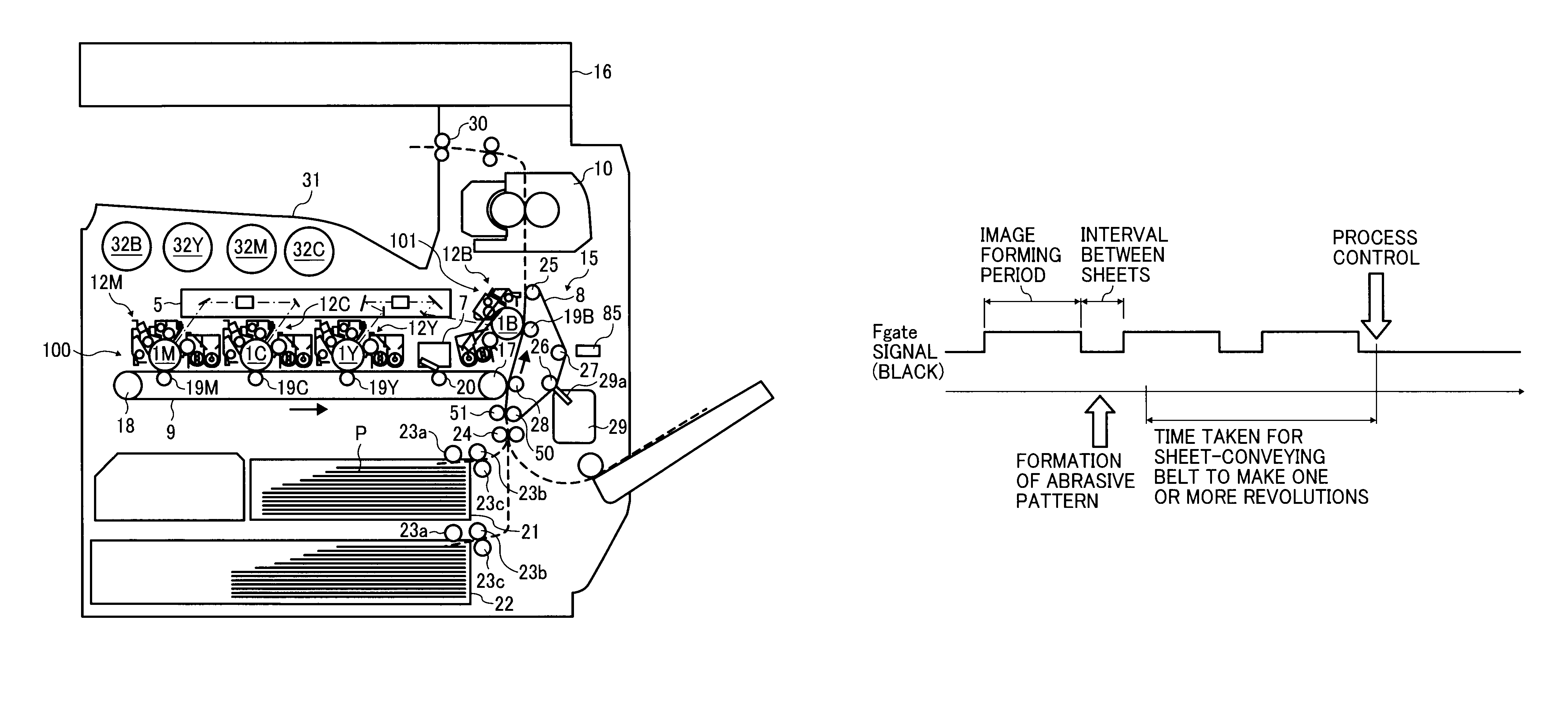
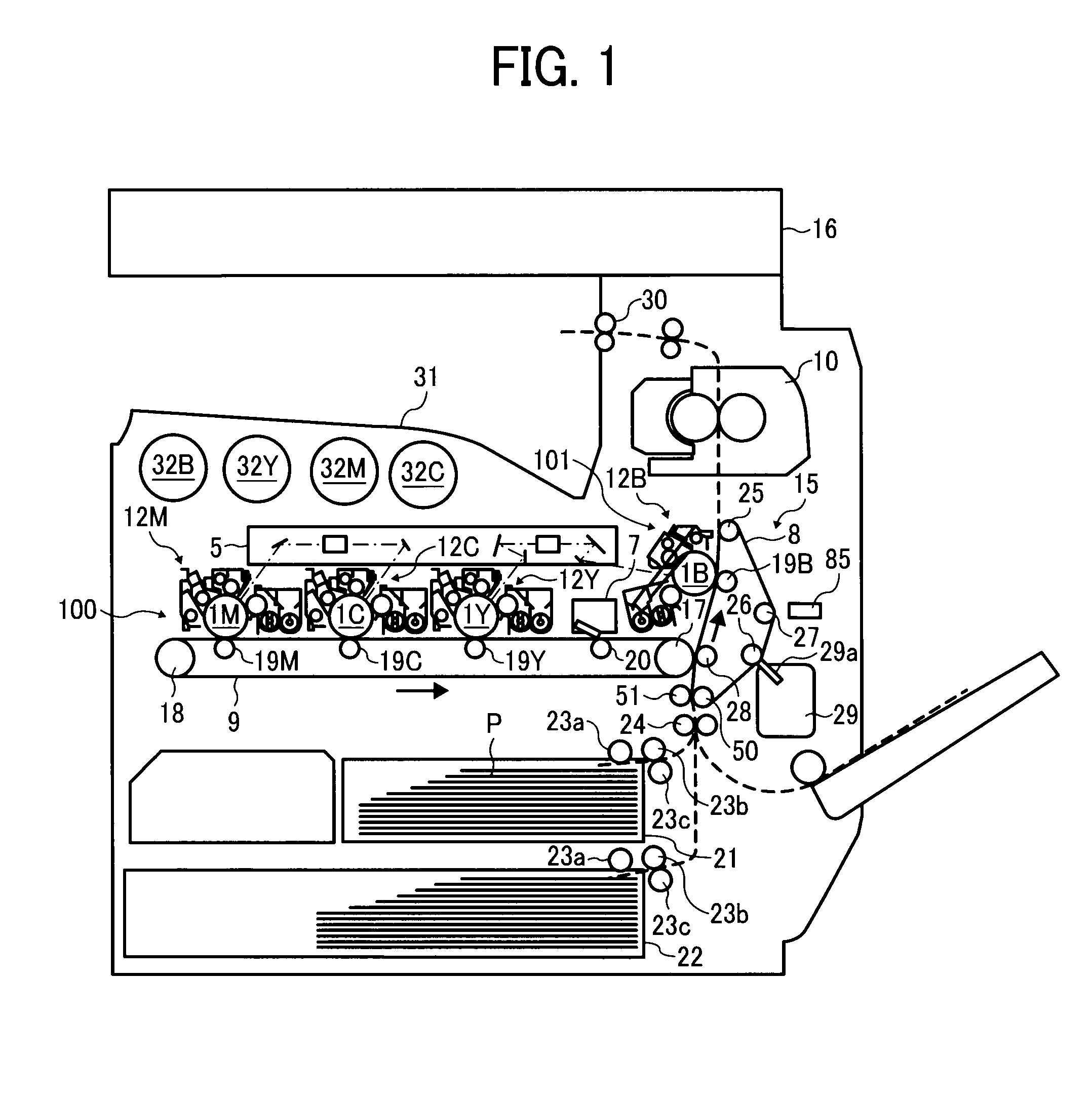
[0026]Exemplary embodiments of the present invention are described in detail below with reference to the accompanying drawings. FIG. 1 is a schematic diagram of an image forming apparatus according to a first embodiment of the present invention. As shown in FIG. 1, the image forming apparatus includes a color-image forming device 100 that corresponds to a first image forming device and a black (B)-image forming device 101 that corresponds to a second image forming device.

[0027]The color-image forming device 100 includes three image forming units 12Y, 12C, and 12M for yellow (Y), cyan (C), and magenta (M) that correspond to first image forming units; an intermediate transfer belt 9 that corresponds to an intermediate transfer member and extends on a substantially horizontal plane in a loop; three primary transfer rollers 19Y, 19C, and 19M that correspond to primary transfer units; and a secondary transfer roller 28 that corresponds to a secondary transfer unit. The image forming unit...

second embodiment

[0099]An image forming apparatus according to a second embodiment of the present invention is described below. The image forming apparatus according to the second embodiment has almost the same configuration as the configuration of the image forming apparatus according to the first embodiment. Only the differences between them are described below.

[0100]FIG. 9 is a schematic diagram of the image forming apparatus according to the second embodiment.

[0101]In the image forming apparatus according to the present embodiment, the black-image forming device is not upstream of the secondary transfer position in the recording-sheet moving direction. The exposing device is under the second image forming device. The intermediate transfer belt is above the image forming units for Y, M, and C.

[0102]As described above, because the black-image forming device is upstream of the secondary transfer position in the recording-sheet moving direction, the color toner images of Y, M, and C do not pass thro...


PUM


Abstract

By using a black-image forming device, an abrasive pattern is formed on a sheet conveying belt so that toner is input to a contact section where a cleaning blade is in contact with the sheet conveying belt. After the toner is input to the contact section where the cleaning blade is in contact with the sheet conveying belt and then the sheet conveying belt makes one or more revolutions, a process control is performed in which Y, M, and C toner patterns and B toner pattern are transferred onto the sheet conveying belt.

Description

CROSS-REFERENCE TO RELATED APPLICATIONS[0001]The present application claims priority to and incorporates by reference the entire contents of Japanese Patent Application No. 2009-209679 filed in Japan on Sep. 10, 2009.BACKGROUND OF THE INVENTION[0002]1. Field of the Invention[0003]The present invention relates to image forming apparatuses, such as printers, facsimile machines, and copying machines.[0004]2. Description of the Related Art[0005]Image forming apparatuses are known that include a plurality of first image carriers, an intermediate transfer member, a first image forming device, a second image carrier, and a second image forming device (e.g., Japanese Patent Application Laid-open No. 2006-201743). The first image carriers are a plurality of photosensitive elements that carry thereon either yellow (Y), magenta (M), or cyan (C) toner images. The intermediate transfer member is an intermediate transfer belt that sequentially receives the Y, M, and C toner images from the photos...

Claims


Application Information

Patent Timeline
Patent Type & Authority Patents(United States)
IPC IPC(8): G03G15/00
CPCG03G15/0194G03G2215/00021G03G2215/0132
Inventor SUZUKI, HIROKATSUSUDO, KAZUHISAKAWASUMI, MASANORIHASHIMOTO, SHUNICHIUNO, MUGIJIROUSHINSHI, AKIRAFURUYA, MASAHARUSATOH, MASAHIKOTAMURA, HIROHMISAITOH, KAZUYATAKAHASHI, TOMOKOSUGANUMA, TAKUYA
Owner RICOH KK
Why Eureka
Try Eureka