Image forming apparatus and method of controlling image forming apparatus

a technology of image forming apparatus and image information, which is applied in the direction of electrographic process, instruments, transportation and packaging, etc., can solve the problems of not being able to collectively manage pieces of information by a digital information database, no attached information as described above can be related to image information any longer, and it is difficult to browse or reuse information concerning printed image information

Inactive Publication Date: 2005-02-03
CANON KK
View PDF8 Cites 162 Cited by
  • Summary
  • Abstract
  • Description
  • Claims
  • Application Information

AI Technical Summary

Benefits of technology

[0009] The present invention has been proposed to solve the conventional problems, and has as its object to provide an image formation technique capable of unitary management of image data, and capable of, for example, retrieving and reusing the image data. The present invention principally has the following arrangements.

Problems solved by technology

Unfortunately, if the original data is not digital data but image information printed on a sheet-like paper medium (to be referred to as a “paper sheet” hereinafter), or if image information is obtained by printing digital data on a printing medium by an image forming apparatus, no attached information as described above can be related to the image information any longer.
Therefore, these pieces of information cannot be collectively managed by a digital information database.
This makes it very difficult to browse or reuse information concerning printed image information.
For example, when image information is once printed on a printing medium on the basis of digital data, the original digital data cannot be retrieved from the medium unless information for retrieving the digital data is present.
Furthermore, if the original digital data is changed or modified by editing later, the result of editing cannot be reflected on the image information printed before editing.
This imposes a repetitive operation burden on an operator.
Also, even when a radio identification tag is used, a read / write tag by which data can be read out from and written in a memory is still expensive compared to a read-only tag (u chip) by which it is only possible to read out data stored in a memory in advance.
Additionally, using a radio identification tag by attaching it to a printing medium beforehand poses many problems in respect of the reliability.
Consequently, a device forming the radio identification tag may be physically destroyed, or may cause dielectric breakdown by a high electric field applied during, for example, transfer inside the image forming apparatus and may become unable to operate.
That is, image formation with a radio identification tag attached to a printing medium beforehand is difficult in respect of the reliability of the radio identification tag.
Also, generally no printing media having radio identification tags attached to them have spread yet, so it is presently difficult to specially order and prepare such printing media in advance.

Method used


Image

  • Image forming apparatus and method of controlling image forming apparatus
  • Image forming apparatus and method of controlling image forming apparatus
  • Image forming apparatus and method of controlling image forming apparatus

Examples


first embodiment

[0054] (First Embodiment)

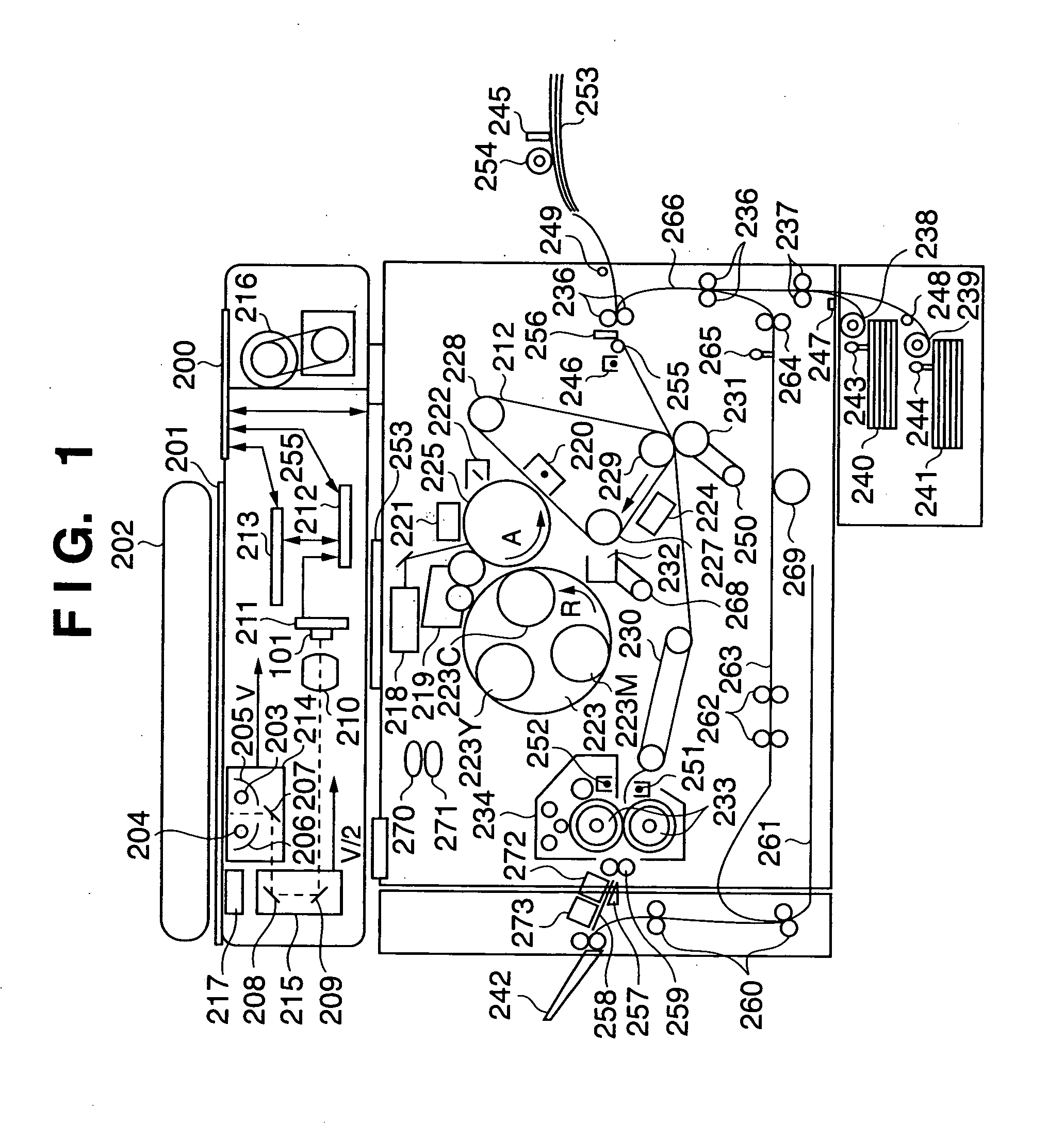
[0055] FIGS. 1 to 3 are views for explaining the arrangement of an image forming apparatus to which an image formation technique provided by the present invention is applied. The basic configurations will be explained below with reference to FIGS. 1 to 3.

[0056]

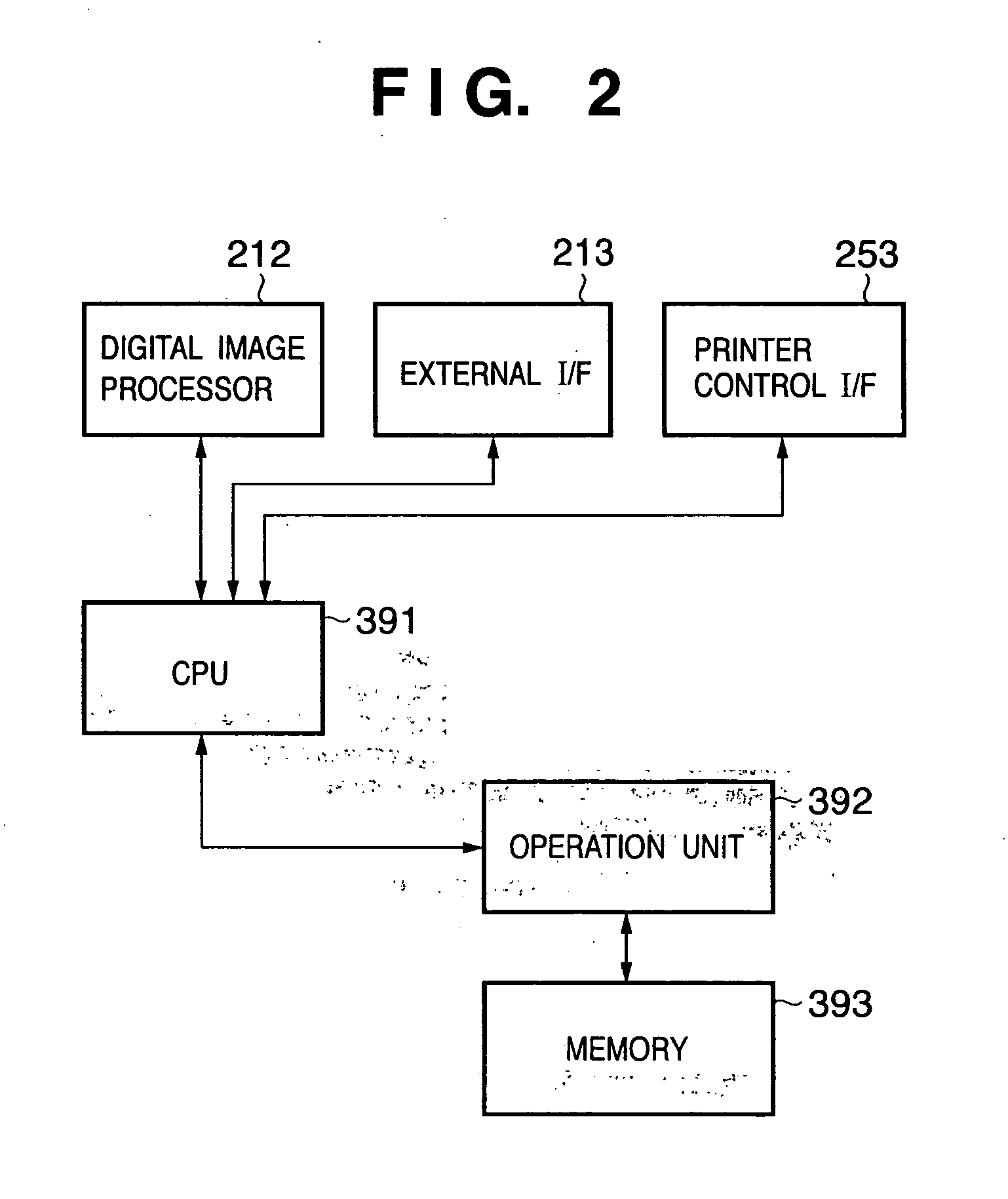
[0057] First, the arrangement of a color reader will be described below. FIG. 1 is a view showing the overall arrangement of the image forming apparatus. In FIG. 1, reference numeral 101 denotes a CCD which is an image sensing element; 211, a substrate on which the CCD 101 is mounted; 200, a controller which controls the whole image forming apparatus; 212, a digital image processor; 201, an original glass plate (platen); and 202, a document feeder (DF) (a mirror-surface press plate may also be used instead of the document feeder 202).

[0058] Reference numerals 203 and 204 denote light sources (halogen lamps or fluorescent lamps) for illuminating an original; 205 and 206, reflectors for condensing ligh...

second embodiment

[0130] (Second Embodiment)

[0131]FIG. 16A is a view for explaining the arrangement of an image forming apparatus according to the second embodiment to which an image formation technique provided by the present invention is applied. The differences from the arrangement of the first embodiment shown in FIG. 1 are that the radio identification tag adhering device 272, radio identification tag information writing device 273, and paper discharge tray 242 are removed, and parts denoted by reference numerals 300 to 330 are added.

[0132]

[0133] The newly added parts will be described below. Reference numerals 300 to 304 denote members forming a paper discharge tray unit of the image forming apparatus. A pole support base 300 fixes a support pole 301 standing upright on the floor surface. The support pole 301 thus fixed by the pole support base 300 has a hollow structure as indicated by the broken lines in FIG. 16A. This allows a movable pole 302 to vertically move in the support pole 301. For...

third embodiment

[0179] (Third Embodiment)

[0180] The contents of the third embodiment will be described below with reference to FIGS. 21 and 22. The arrangement shown in FIG. 21 differs from FIG. 16A of the second embodiment in that a unit 350 (to be referred to as a “radio identification tag information receiving unit” hereinafter) corresponding to a radio identification tag information receiver 217 of a color reader) is added. The other components are denoted by the same reference numerals as in the second embodiment, and a repetitive explanation thereof will be omitted.

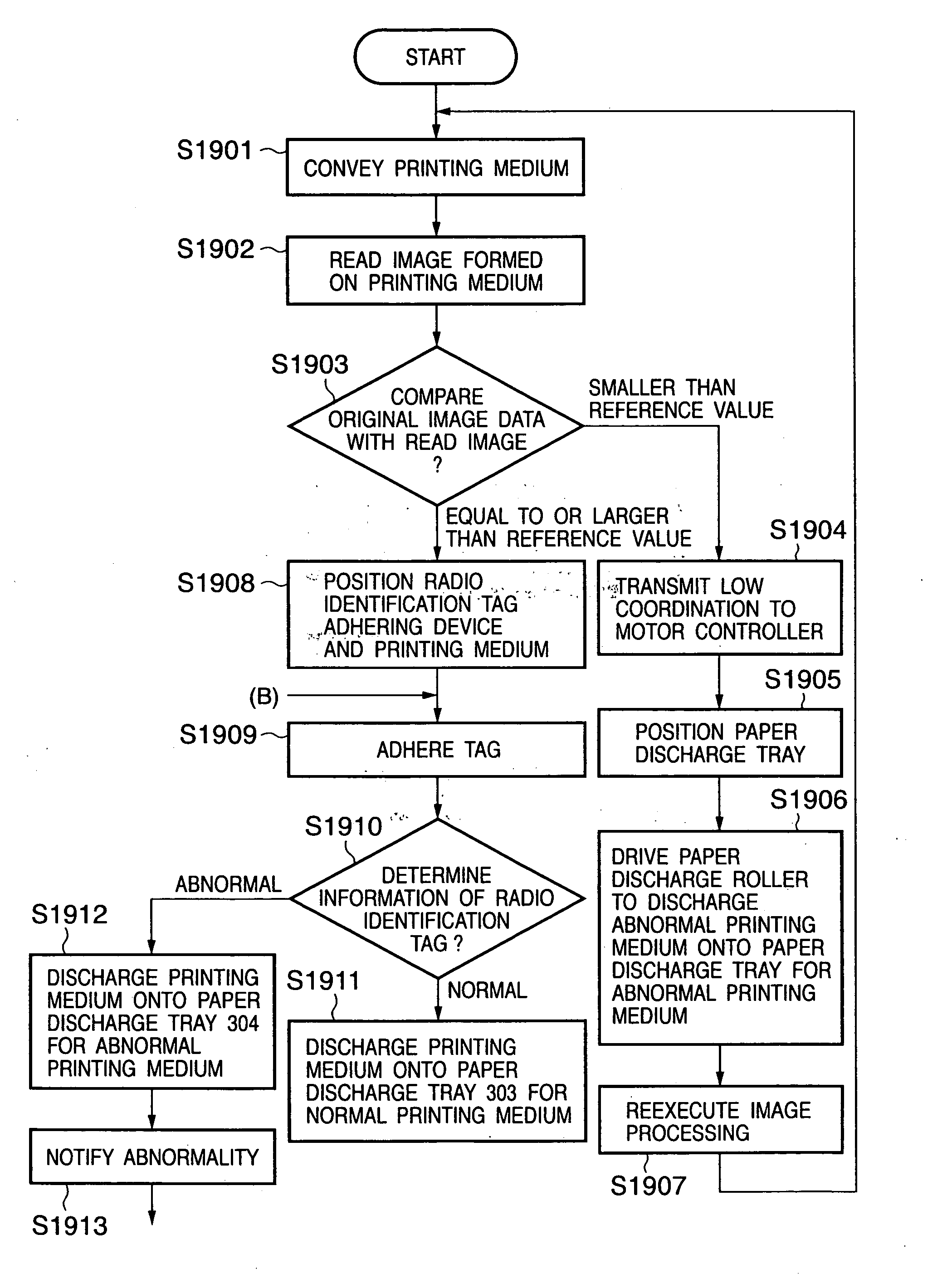
[0181]FIG. 22 is a flowchart showing the flow of processing according to the third embodiment. The contents of this embodiment will be described below with reference to FIGS. 21 and 22.

[0182] In step S2201, conveyance of a printing medium is started. Printing media stored in cassettes (240 and 241) and a manual paper feed unit 253 are conveyed one by one onto a paper feed path by pickup rollers (238, 239, and 254). The radio iden...


PUM

PropertyMeasurementUnit
adhesionaaaaaaaaaa
temperatureaaaaaaaaaa
dielectric breakdownaaaaaaaaaa

Abstract

An image forming apparatus by which an image formed on a printing medium by image forming means on the basis of image data can be related to the image data includes a controller which prepares management information corresponding to the image data, and controls an operation of the image forming means in accordance with the management information, an adhering unit which adheres, to the printing medium on which the image is formed by the image forming means, a radio identification tag having a transmitting/receiving unit capable of transmitting/receiving data by radio communication, and a data holding unit capable of holding the data, and a communicating module which writes, in the data holding unit of the radio identification tag adhered on the printing medium, the management information for relating the image on the printing medium to the image data, by communicating with the transmitting/receiving unit by radio.

Description

FIELD OF THE INVENTION [0001] The present invention relates to an image formation technique and, more particularly, to an image forming apparatus which forms an image by transferring, onto a printing medium, a toner image formed on a latent image carrier by, for example, an electrophotographic method or electrostatic printing method, or an image forming apparatus which directly forms an image on a printing medium by an ink-jet printing method, and a method of controlling the image forming apparatus. BACKGROUND OF THE INVENTION [0002] In an electrophotographic image forming apparatus which forms a copied image by transferring a toner latent image formed on a transfer medium onto printing media such as plain paper sheets stored in a paper feed unit, and thermally fixes the transferred toner latent image, it is important to manage image information having undergone copied image formation, in order to browse and reuse the information concerning the copied image. When image information o...

Claims


Application Information

Patent Timeline
Patent Type & Authority Applications(United States)
IPC IPC(8): G03G15/00B41J29/38G03G21/00G06K17/00G06K19/07H04N1/00
CPCG03G15/65G03G2215/00751G03G2215/00611G03G2215/00447
Inventor KONDO, SHUNSAKUTANABE, MASATOSHIHAYASHI, TOSHIOFUNAMIZU, YOSHIHIROISEMURA, KEIZOMURATA, MITSUSHIGEINTO, JUNICHI
Owner CANON KK
Why Eureka
Try Eureka