Image-forming device and developer cartridge for use therein

a technology of image-forming device and developer cartridge, which is applied in the direction of instruments, electrographic process apparatus, optics, etc., can solve the problems of increasing the cost and complexity of the developing device, affecting the quality of the image-forming cartridge, and not being able to detect the developer cartridge. , to achieve the effect of avoiding an increase in structural complexity and suppressing a rise in manufacturing costs

Active Publication Date: 2006-08-31
BROTHER KOGYO KK
View PDF16 Cites 154 Cited by
  • Summary
  • Abstract
  • Description
  • Claims
  • Application Information

AI Technical Summary

Benefits of technology

[0011] In view of the foregoing, it is an object of one aspects of the present invention to provide an image-forming device capable of determining information on a developer cartridge, while suppressing a rise in manufacturing costs and avoiding an increase in structural complexity. It is another object of the present invention to provide a developer cartridge detachably mounted in the image-forming device.

Problems solved by technology

Accordingly, this structure increases the cost and complexity of the developing device.
However, since the toner accommodated in these developer cartridges has different agitation properties based on the amount of toner, rates of degradation of the toner is also different based on the amount of toner.
Under these circumstances, it is not sufficient merely to detect whether the developer cartridge is a new product since the life of the developer cartridge from this point of detection may differ according to the amount toner accommodated therein.
Accordingly, the life of the developer cartridge cannot be accurately determined.
As a result, a developer cartridge accommodating a small amount of toner may actually reach the end of its life before such a determination is made, resulting in a decline in image quality.

Method used


Image

  • Image-forming device and developer cartridge for use therein
  • Image-forming device and developer cartridge for use therein
  • Image-forming device and developer cartridge for use therein

Examples


Embodiment Construction

[0043] An image-forming device according to preferred embodiments of the present invention will be described while referring to the accompanying drawings wherein like parts and components are designated by the same reference numerals to avoid duplicating description.

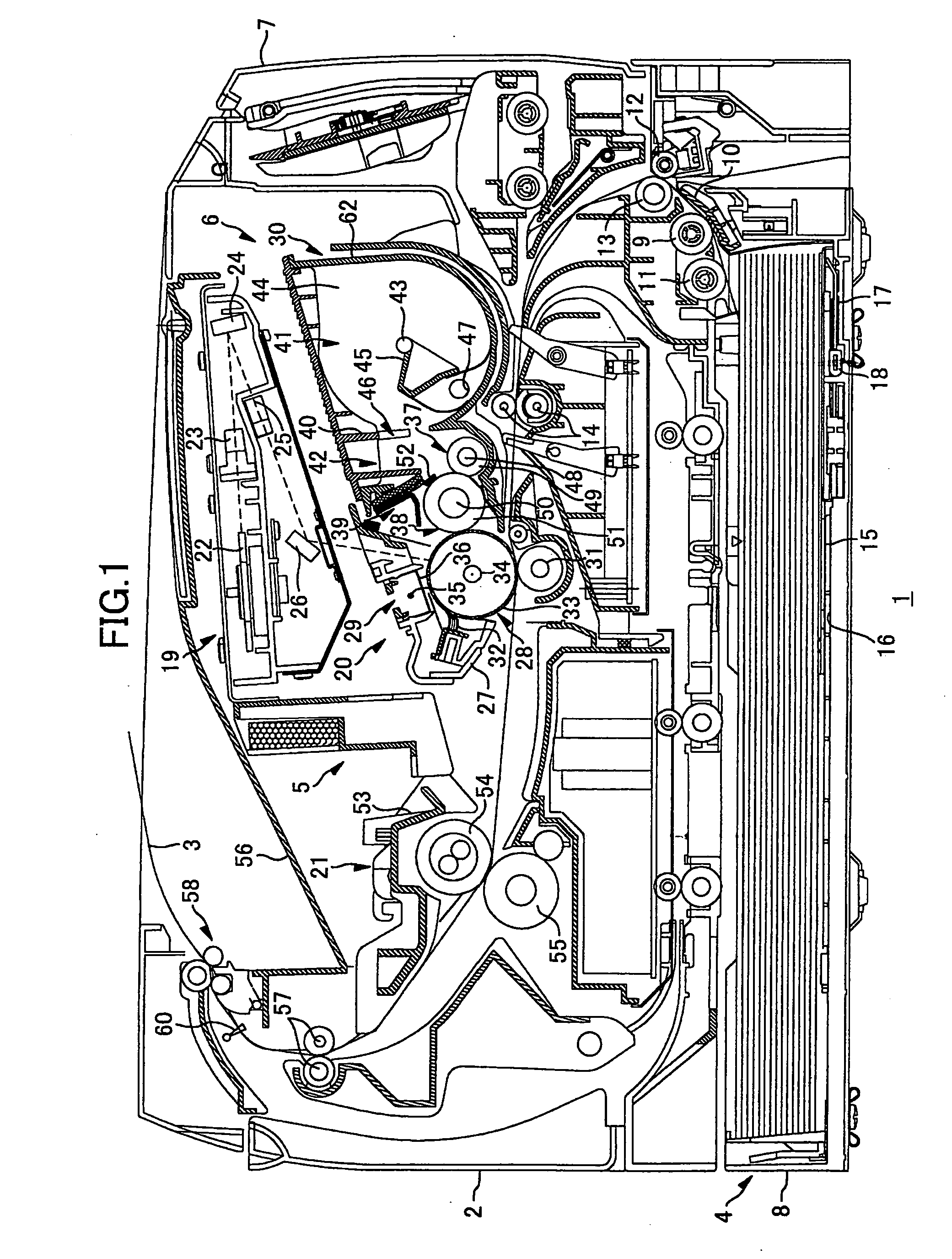
[0044] 1. Overall Structure of a Laser Printer

[0045]FIG. 1 is a side cross-sectional view of a laser printer 1 serving as the image-forming device of the present invention. As shown in FIG. 1, the laser printer 1 includes a main casing 2 and, within the main casing 2, a feeding unit 4 for supplying sheets of a paper 3, an image-forming unit 5 for forming images on the paper 3 supplied by the feeding unit 4, and the like.

[0046] (1) Main casing

[0047] An access opening 6 for inserting and removing a process cartridge 20 described later, and a front cover 7 capable of opening and closing over the access opening 6 is formed in one side wall of the main casing 2. The front cover 7 is rotatably supported by a cover shaft (n...


PUM


Abstract

When a new developer cartridge is initially mounted in an image-forming device, a toothed part of a sensor gear disposed in the cartridge is brought into meshing engagement with an agitator drive gear disposed in the image-forming device. The sensor gear is driven while its toothed part is in meshing engagement with the agitator drive gear and driving of the sensor gear is stopped when its toothless part opposes the agitator drive gear. One or more contact protrusions are formed on the sensor gear to be movable therewith. An information-detecting mechanism detects how many contact protrusions are formed on the sensor gear during driving of the sensor gear. Based on the detection results, whether the mounted developer cartridge is a new product or not is determined, and information on the maximum sheets to be printed with the mounted developer cartridge is acquired.

Description

CROSS REFERENCE TO RELATED APPLICATION [0001] This application claims priorities from Japanese Patent Applications No. 2005-055104, filed Feb. 28, 2005 and No. 2005-180962, filed Jun. 21, 2005, the entire subject matter of which is incorporated herein by reference. BACKGROUND OF THE INVENTION [0002] 1. Field of the Invention [0003] The present invention relates to an image-forming device such as a laser printer, and a developer cartridge detachably mounted in the image-forming device. [0004] 2. Description of the Related Art [0005] In conventional laser printers, developer cartridges accommodating toner are detachably mounted therein. This type of laser printer is provided with new product detecting means for detecting whether the developer cartridge mounted in the laser printer is a new product and for determining the life of the developer cartridge from the point that the new product was detected. [0006] For example, Japanese unexamined patent application publication No. 2000-2217...

Claims


Application Information

Patent Timeline
Patent Type & Authority Applications(United States)
IPC IPC(8): G03G15/00
CPCG03G21/1896G03G2215/066G03G2221/163G03G15/0855G03G15/0875G03G15/0865G03G2221/1892
Inventor SUZUKI, TSUTOMUTAKAGI, TAKEYUKIKAJIKAWA, YOSHIFUMI
Owner BROTHER KOGYO KK
Why Eureka
Try Eureka