Firearm suppressor booster system

a booster system and suppressor technology, applied in the field of suppressors, can solve the problems of affecting the effect of suppressors or silencers, affecting the performance of firearms, and causing firearm jamming

Active Publication Date: 2013-04-23
JJE BRANDS LLC
View PDF192 Cites 50 Cited by
  • Summary
  • Abstract
  • Description
  • Claims
  • Application Information

AI Technical Summary

Problems solved by technology

Thus, the firearm will jam.
The added length is typically seen as undesirable.

Method used


Image

  • Firearm suppressor booster system
  • Firearm suppressor booster system
  • Firearm suppressor booster system

Examples


Embodiment Construction

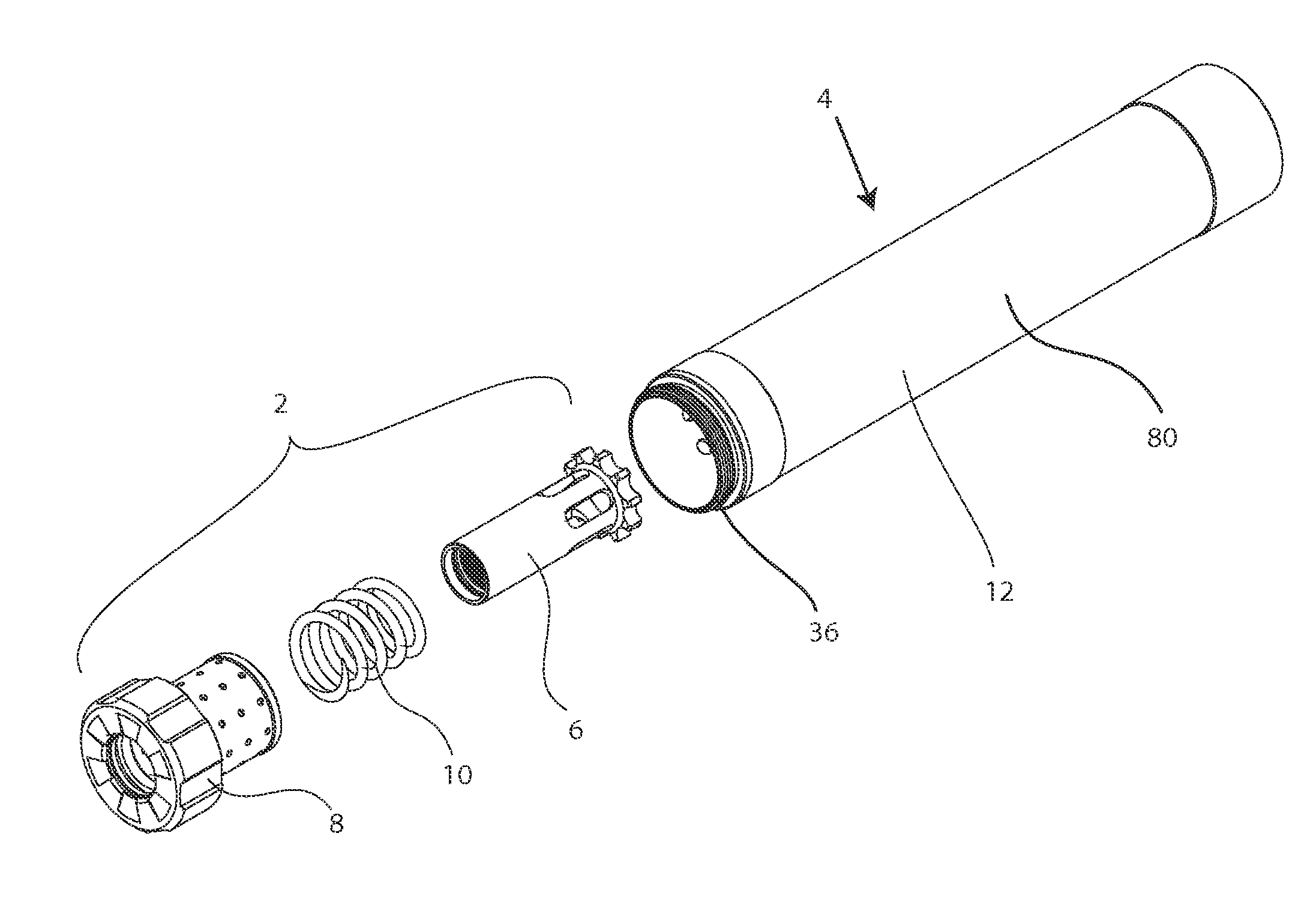
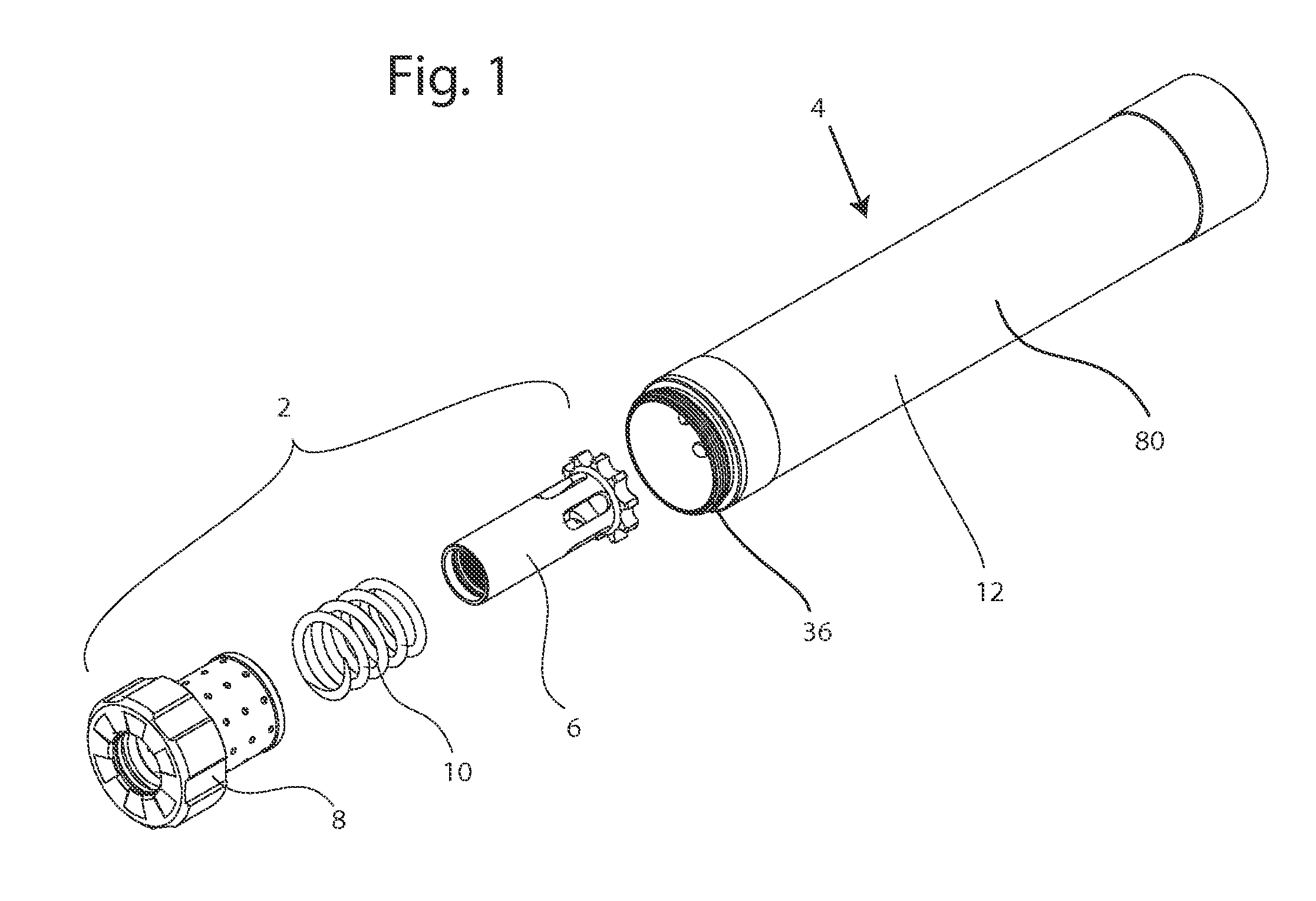
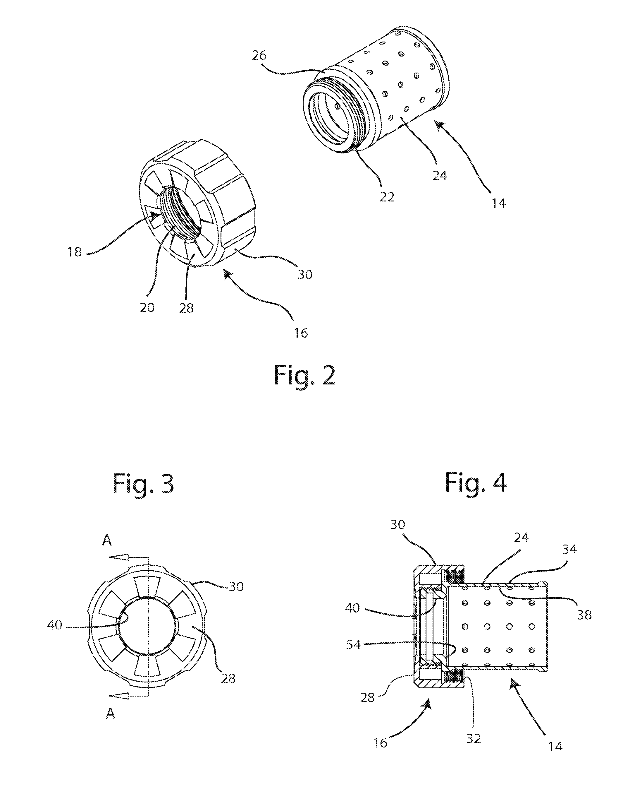
[0021]As shown in FIG. 1, a booster system 2 in accordance with an embodiment of the present invention may be integrally incorporated with a firearm suppressor or silencer 4. The booster system 2 generally includes a piston 6, a piston housing assembly 8 and a spring 10. The piston 6 includes a first attachment for attaching to the barrel of a firearm, and the piston housing assembly 8 includes an attachment for attaching to a body 12 of the silencer 4. When assembled, the piston 6 is disposed within the piston housing 8, and the spring 10 provides a relative spring force between the piston 6 and piston housing 8 with the spring 10 urging the piston 6 forward and urging the piston housing 8 backward. When a projectile is fired from the firearm, it passes through a bore in the piston 6. The recoil of the firearm allows the piston 6 and barrel to move backward with respect to the piston housing assembly 8 and the rest of the silencer 4. As a result, the spring 10 is compressed. With t...


PUM


Abstract

A booster system including a piston housing, a piston, a spring, and a rear cap attached to the piston housing. The piston housing includes an annular outer wall and an annular projection extending inward from the outer wall at a rear end of the piston housing. The piston is disposed within the piston housing and includes a bore and a radially outwardly extending flange at its front end. The spring is radially disposed between the piston housing and the piston in a space enclosed by the outwardly extending flange and the annular projection. The rear cap includes an end wall extending radially outward from a rear end of the piston housing. A side wall extends forward from the end wall and hangs over the outer wall of the piston housing at a radial distance from the outer wall of the piston housing. The sidewall of the rear cap includes an engagement surface for attachment to a body of a silencer.

Description

CROSS-REFERENCE TO RELATED APPLICATION[0001]This application claims the benefit of and priority to U.S. Provisional Patent Application No. 61 / 274,738, filed Aug. 20, 2009, which is hereby incorporated by reference in its entirety.FIELD[0002]The present invention relates to firearm suppressors, and particularly relates to a booster system for a firearm suppressor or silencer.BACKGROUND[0003]Many semi-automatic handguns employ a short recoil action to feed a fresh cartridge into the chamber after firing. During the short recoil action the barrel and slide travel rearward a short distance together in a locked position until a mechanism causes the barrel to tilt downward. At this point the tilting barrel disengages from the slide which continues traveling rearward until it extracts the fired cartridge case and feeds a new cartridge into the chamber. A spring force causes the slide to return forward, the barrel to tilt up and reengage with the slide, and the locked barrel and slide to re...

Claims


Application Information

Patent Timeline
Patent Type & Authority Patents(United States)
IPC IPC(8): F41A21/38
CPCF41A21/26F41A21/30
Inventor BRITTINGHAM, KEVINSMITH, MICHAEL LEIGHTON
Owner JJE BRANDS LLC
Why Eureka
Try Eureka