Noise suppression device

a noise suppression and device technology, applied in the direction of transducer casings/cabinets/supports, electrical transducers, instruments, etc., can solve the problems of inability to achieve noise suppression processing. to achieve the effect of suppressing residual noise, minimizing distortion of intended signals, and suppressing residual nois

Inactive Publication Date: 2006-05-09
MITSUBISHI ELECTRIC CORP
View PDF4 Cites 62 Cited by
  • Summary
  • Abstract
  • Description
  • Claims
  • Application Information

AI Technical Summary

Benefits of technology

[0016]The noise suppressor stated above is capable of suppressing residual noises through execution of spectral subtraction processing after completion of the perceptual weighting relative to the average noise spectrum and further by use o

Problems solved by technology

Unfortunately, these advantages do not come without accompanying problems which follow.
Another problem faced with the related art is that in audio domains, it is impossible or at least greatly difficult to suppress residual noises without suppressing an audio signal waveform per se, which would disadvantageously result in a decrease in sound volume of audio and/or voice data.
Still another problem encountered with the related art lies in inherent limitations to the performance of noise suppression processing, which merely relies upon noise removal coefficient control schemes based on perceptual weighting of the average noise spectrum.
This can be said because such related art approach is incapable of suppressing “special” noises that can occur in special environments.
One example is that in highly noisy environments such as inside of a land vehicle that is running on express motorways or highways, the prediction accuracy of the avera

Method used


Image

  • Noise suppression device
  • Noise suppression device
  • Noise suppression device

Examples


embodiment 1

[0050]An explanation will now be given of a noise suppression device incorporating the principles of this invention, with reference to the accompanying drawings.

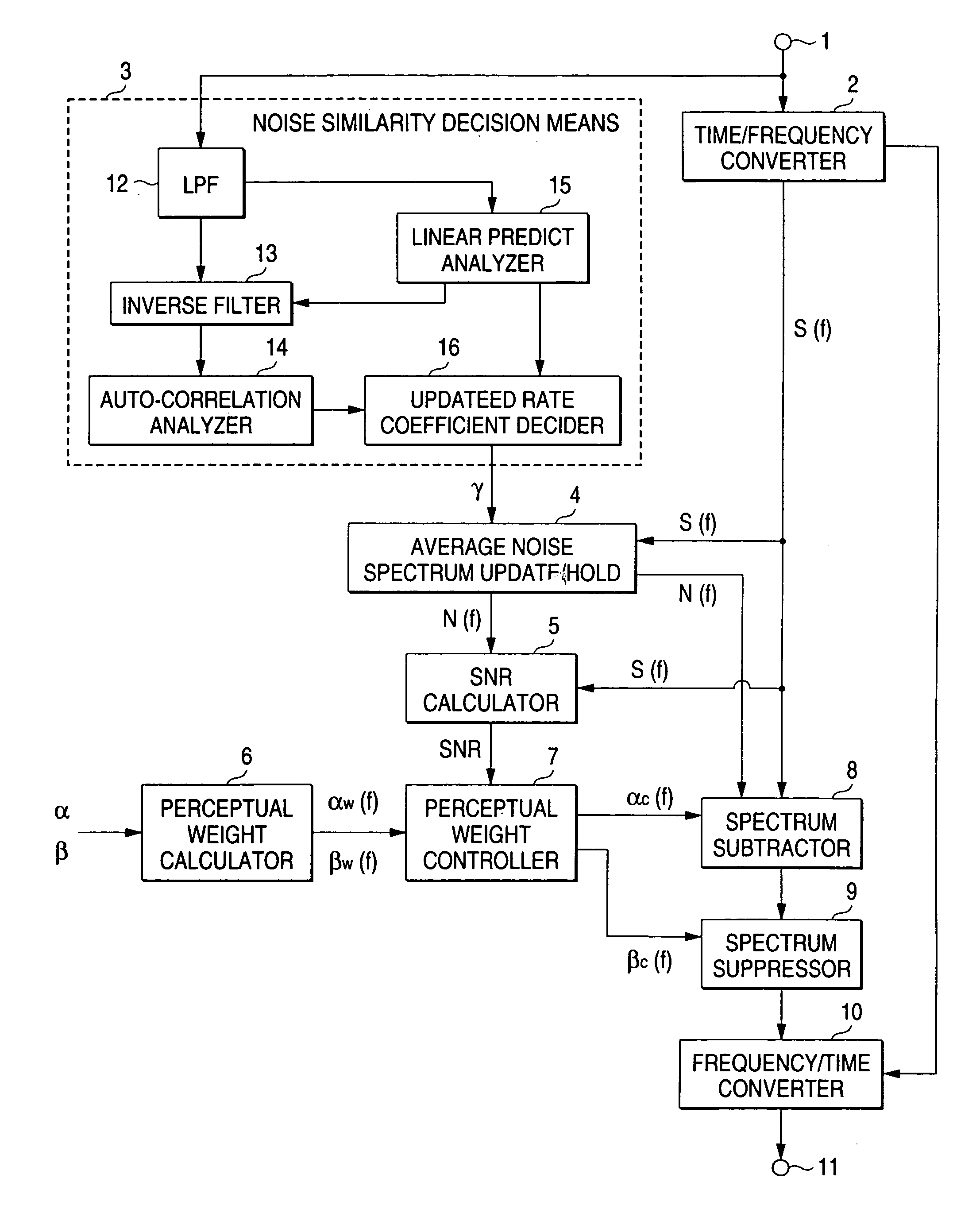
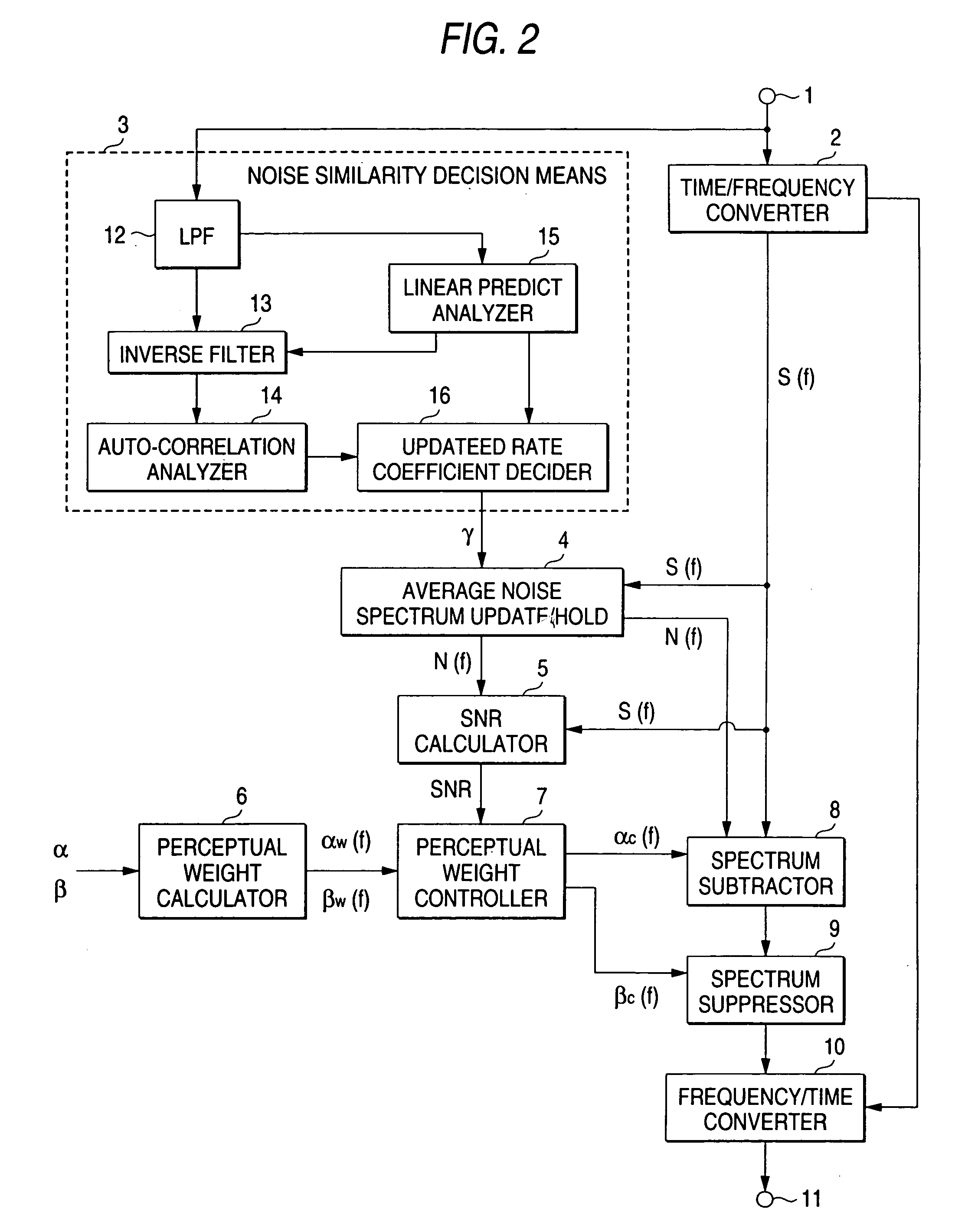
[0051]FIG. 2 is a block diagram showing a configuration of a noise suppressor device in accordance with an embodiment 1 of the present invention. The illustrative noise suppressor is generally constituted from an input signal receive terminal 1, a time-to-frequency (time / frequency) converter circuit 2, a noise similarity analyzer circuit 3, an average noise spectrum update and storage circuit 4, a signal-to-noise ratio (SNR) calculator circuit 5, a perceptual weight calculator circuit 6, a perceptual weighting control circuit 7, a spectrum subtractor circuit 8, a spectrum suppressor circuit 9, a frequency / time converter circuit 10, and an output signal terminal 11. The principles of an operation of the noise suppressor embodying the present invention will be explained in conjunction with FIG. 2 below.

[0052]An input signal is...

embodiment 2

[0086]Another implementable form of the embodiment 1 is available, which is arranged so that the average spectrum of a present frame's input signal amplitude spectrum and average noise spectrum is subdivided into portions corresponding to a low frequency region and high frequency region for obtaining a low frequency power and a high frequency power to determine a ratio of the low frequency power versus high frequency power, which ratio is then used to modify the first perceptual weight and the second perceptual weight.

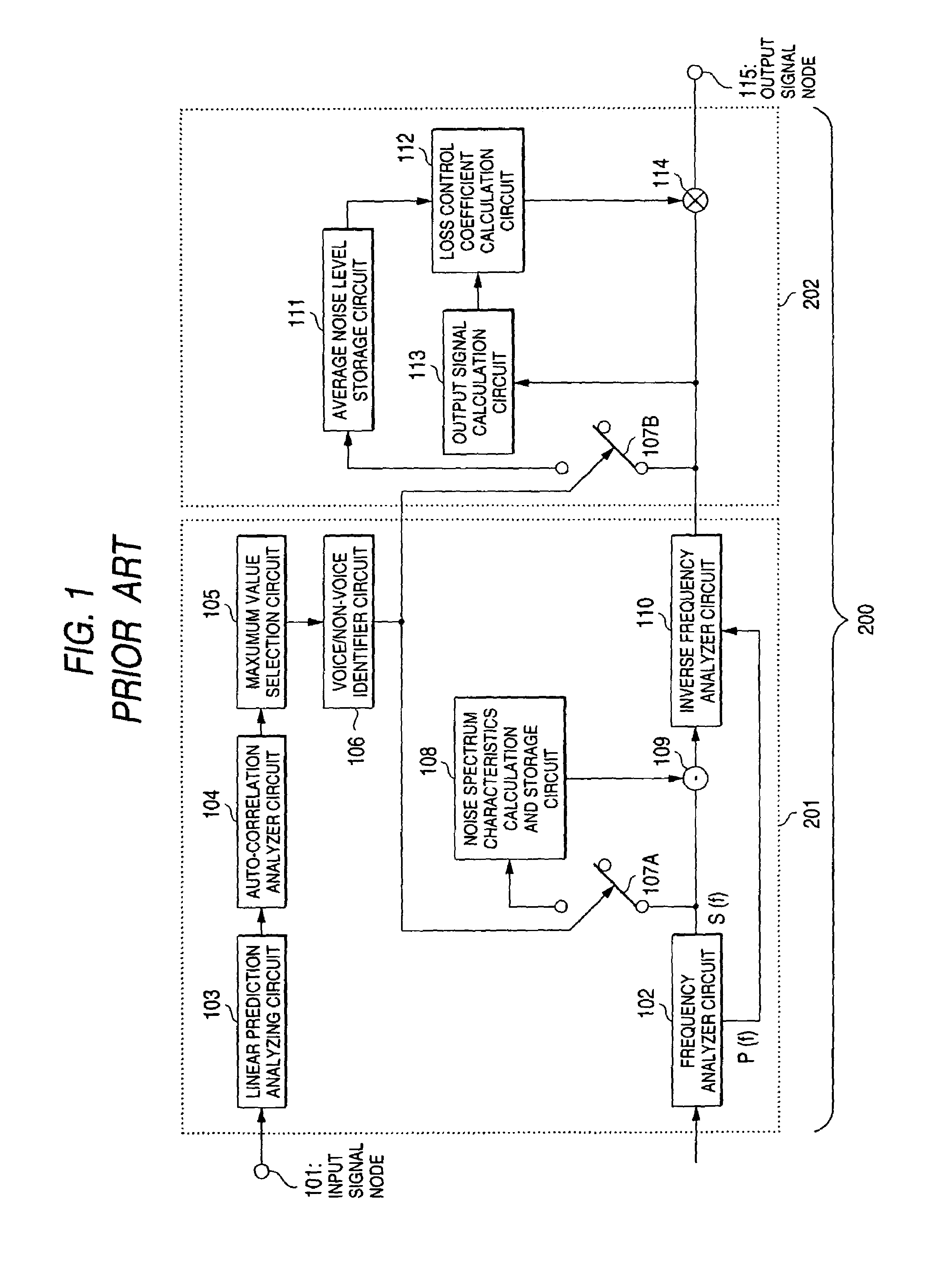
[0087]FIG. 11 is a block diagram showing a configuration of a noise suppressor device in accordance with the embodiment 2 of the present invention, wherein the same or corresponding components to those of the embodiment 1 shown in FIG. 2 are designated by the same reference characters. One principal difference of the former over the latter is that a perceptual weight modifying circuit 17 is newly added. The remaining parts are the same as those of FIG. 1; thus, an expl...

embodiment 3

[0094]Another form of the embodiment 2 is available when reduction to practice of this invention, which is arranged so that the perceptual weight modifier circuit 17 is designed to obtain, as the alternative of the average spectrum of the input signal amplitude spectrum and average noise spectrum, a low frequency power and high frequency power after subdivision of the input signal spectrum alone into its low frequency region and high frequency region, and then modify the first perceptual weight and second perceptual weight at a ratio of such low frequency power versus high frequency power.

[0095]As the modification of the first perceptual weight and second perceptual weight at the ratio of the low frequency power and high frequency power of an input signal amplitude spectrum makes it possible to attain the intended perceptual weighting of the spectrum removal and spectrum amplitude suppression in accordance with the frequency characteristics of an input audio spectrum; accordingly, i...


PUM


Abstract

A noise suppressor device for attaining perceptually preferable noise suppression is disclosed. The device minimizes reduction in quality even in the presence of increased noises. The device is adaptable for use in voice communications systems and speech recognition systems employed in a variety of kinds of noisy environments. The device includes a spectrum subtracter and a spectrum amplitude suppressor that operate on the basis of perceptual weights.

Description

BACKGROUND OF THE INVENTION[0001]1. Field of the Invention[0002]The present invention relates generally to noise suppression devices for reducing or suppressing noises other than objective signals in voice communications systems and speech recognition systems often used in various noisy environments.[0003]2. Description of the Prior Art[0004]Noise suppressor devices for suppressing any possible nonobjective signal components such as noises mixed into audio / voice signals are known in the art, one of which has been disclosed in, for example, Japanese Patent Laid-Open No. 212196 / 1997. The noise suppressor as taught by this Japanese publication is inherently designed to employ what is called the spectral subtraction method. This method is for noise reduction based on amplitude spectra in a way as suggested from Steven F. Boll, “Suppression of Acoustic Noise in Speech using Spectral Subtraction,” IEEE Trans. ASSP, Vol. ASSP-27, No. 2, April 1979.[0005]The prior known noise suppression te...

Claims


Application Information

Patent Timeline
IPC IPC(8): H04B15/00G10L15/20G10L15/00G10L21/0208G10L21/0232G10L25/78
CPCG10L21/0208G10L21/0264
Inventor FURUTA, SATORU
Owner MITSUBISHI ELECTRIC CORP
Why Eureka
Try Eureka