Cyclonic separating apparatus
a technology of cyclonic separation and vortex finder plate, which is applied in the direction of liquid separation agent, dispersed particle filtration, application, etc., can solve the problems of complex manufacturing process, high cost of tool b>22/b>, and high cost of making each vortex finder plate b>10/b> using the tool b>22/b>, so as to achieve the effect of simple and cheaper production of the vortex finder pla
- Summary
- Abstract
- Description
- Claims
- Application Information
AI Technical Summary
Benefits of technology
Problems solved by technology
Method used
Image
Examples
first embodiment
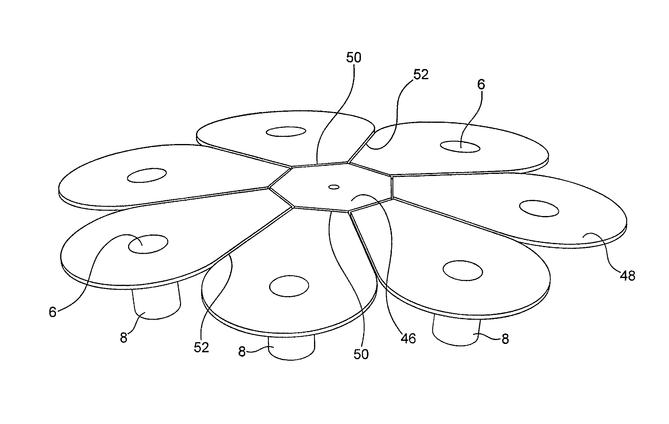
[0051]With reference to FIGS. 3a and 3b the structure of a vortex finder plate 10 according to the present invention is shown. The vortex finder plate 10 comprises a support structure 46 and a plurality of vortex finder support flaps 48. A single vortex finder 8 projects downwardly from each vortex finder support flap 48. A hinge 50 in the form of an area or line of reduced thickness is provided between the support structure 46 and each of the vortex finder support flaps 48. The vortex finder support flaps 48 are not connected to each other. There may, for example, be a split line or a gap 52 between adjacent vortex finder support flaps 48. This arrangement allows the vortex finder support flaps 48 to move or flex about their hinges 50 such that the vortex finder plate 10 can be manufactured in the first position shown in FIG. 3a and then after manufacture the vortex finder support flaps 48 can be moved about their respective hinges 50 into the second position shown in FIG. 3b. In F...
second embodiment
[0055]FIGS. 5a to 5d show vortex finder plate 10 according to the present invention. It can be seen that the vortex finder plate 10 comprises a ring shaped support structure 46, a plurality vortex finder support flaps 48 and a downwardly extending air duct 54. A single vortex finder 8 projects downwardly from each vortex finder support flap 48. A hinge 50 in the form of an area or line of reduced thickness is provided between the support structure 46 and each of the vortex finder support flaps 48. The vortex finder support flaps 48 are not connected to each other. There may therefore be a split or gap 52 between adjacent vortex finder support flaps 48. This arrangement allows the vortex finder support flaps 48 to move or flex about their hinges 50 such that the vortex finder plate 10 can be manufactured in the first position shown in FIGS. 5a and 5b, and then after manufacture the vortex finder support flaps 48 can be moved about their respective hinges 50 into the second position s...
PUM
| Property | Measurement | Unit |
|---|---|---|
| angle | aaaaa | aaaaa |
| thickness | aaaaa | aaaaa |
| size | aaaaa | aaaaa |
Abstract
Description
Claims
Application Information
 - R&D
- Intellectual Property
- Life Sciences
- Materials
- Tech Scout
- Unparalleled Data Quality
- Higher Quality Content
- 60% Fewer Hallucinations
Browse by: Latest US Patents, China's latest patents, Technical Efficacy Thesaurus, Application Domain, Technology Topic, Popular Technical Reports.
© 2025 PatSnap. All rights reserved.Legal|Privacy policy|Modern Slavery Act Transparency Statement|Sitemap|About US| Contact US: help@patsnap.com


