Cyclonic separating apparatus

a technology of cyclonic separation and vortex finder plate, which is applied in the direction of liquid separation agent, dispersed particle filtration, application, etc., can solve the problems of complex manufacturing process, high cost of tool b>22/b>, and high cost of making each vortex finder plate b>10/b> using the tool b>22/b>, so as to achieve the effect of simple and cheaper production of the vortex finder pla

Inactive Publication Date: 2011-09-01
DYSON TECH LTD
View PDF8 Cites 18 Cited by
  • Summary
  • Abstract
  • Description
  • Claims
  • Application Information

AI Technical Summary

Benefits of technology

[0020]This means that there is no undercut to deal with during manufacture making production of the vortex finder plate simpler and cheaper.

Problems solved by technology

Vacuum cleaners are often made from parts which can be complicated and expensive to manufacture.
Such a tool 22 is therefore expensive to make and the process for making each vortex finder plate 10 using the tool 22 is complex.
The problems associated with making a vortex finder plate can become even more complex if it is desired to integrate other components of a cyclonic separating apparatus with the vortex finder plate.

Method used


Image

  • Cyclonic separating apparatus
  • Cyclonic separating apparatus
  • Cyclonic separating apparatus

Examples


first embodiment

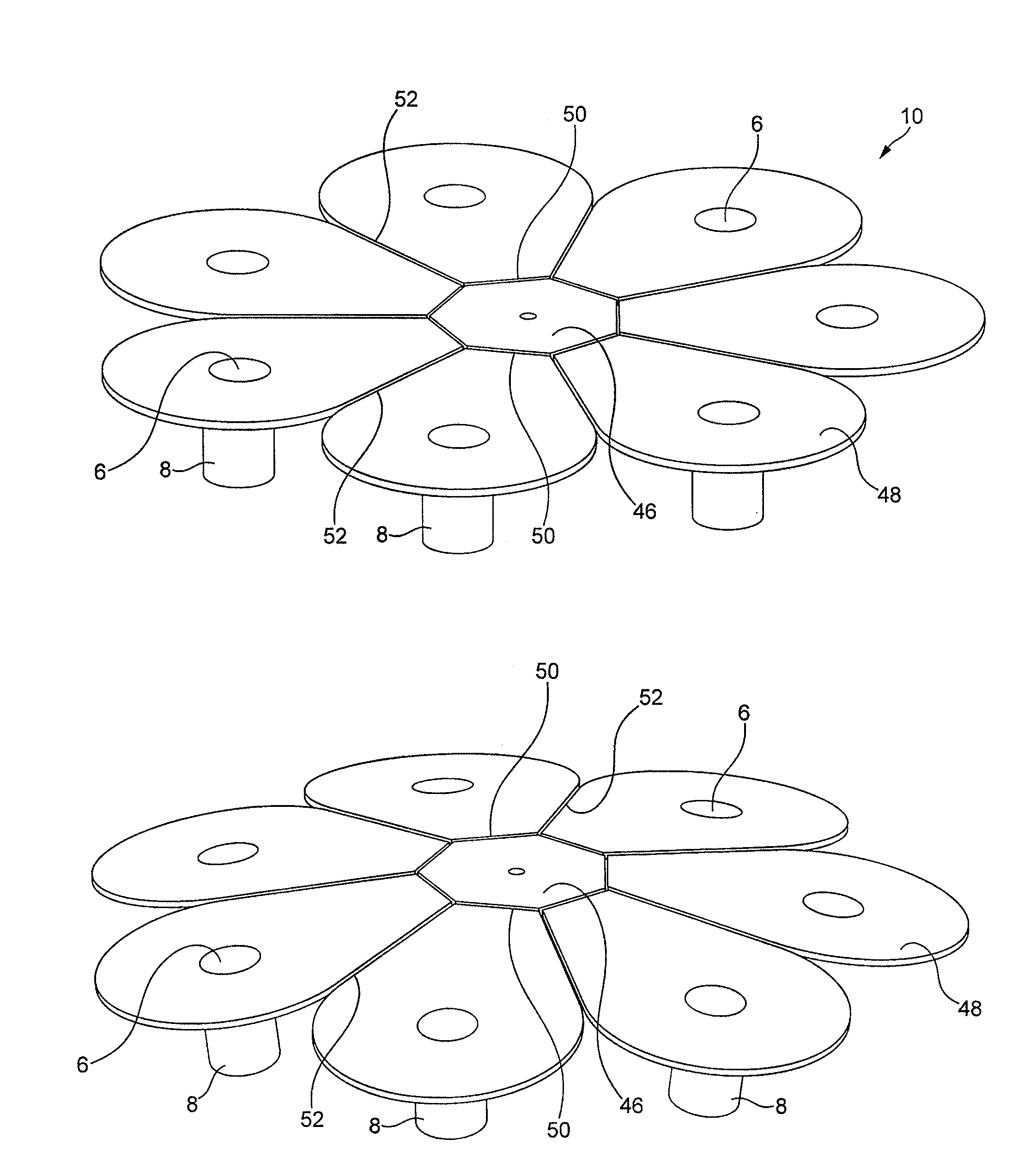
[0051]With reference to FIGS. 3a and 3b the structure of a vortex finder plate 10 according to the present invention is shown. The vortex finder plate 10 comprises a support structure 46 and a plurality of vortex finder support flaps 48. A single vortex finder 8 projects downwardly from each vortex finder support flap 48. A hinge 50 in the form of an area or line of reduced thickness is provided between the support structure 46 and each of the vortex finder support flaps 48. The vortex finder support flaps 48 are not connected to each other. There may, for example, be a split line or a gap 52 between adjacent vortex finder support flaps 48. This arrangement allows the vortex finder support flaps 48 to move or flex about their hinges 50 such that the vortex finder plate 10 can be manufactured in the first position shown in FIG. 3a and then after manufacture the vortex finder support flaps 48 can be moved about their respective hinges 50 into the second position shown in FIG. 3b. In F...

second embodiment

[0055]FIGS. 5a to 5d show vortex finder plate 10 according to the present invention. It can be seen that the vortex finder plate 10 comprises a ring shaped support structure 46, a plurality vortex finder support flaps 48 and a downwardly extending air duct 54. A single vortex finder 8 projects downwardly from each vortex finder support flap 48. A hinge 50 in the form of an area or line of reduced thickness is provided between the support structure 46 and each of the vortex finder support flaps 48. The vortex finder support flaps 48 are not connected to each other. There may therefore be a split or gap 52 between adjacent vortex finder support flaps 48. This arrangement allows the vortex finder support flaps 48 to move or flex about their hinges 50 such that the vortex finder plate 10 can be manufactured in the first position shown in FIGS. 5a and 5b, and then after manufacture the vortex finder support flaps 48 can be moved about their respective hinges 50 into the second position s...


PUM

PropertyMeasurementUnit
angleaaaaaaaaaa
thicknessaaaaaaaaaa
sizeaaaaaaaaaa

Abstract

The present invention relates to a cyclonic separating apparatus and a vortex finder plate for use in a cyclonic separating apparatus, the vortex finder plate including a support structure and a plurality of vortex finder support flaps extending from the support structure, each vortex finder support flap comprising a vortex finder. At least one of the vortex finder support flaps is connected to the support structure by a hinge.

Description

REFERENCE TO RELATED APPLICATIONS[0001]This application claims the priority of United Kingdom Application No. 1003284.5, filed Feb. 26, 2010, the entire contents of which are incorporated herein by reference.FIELD OF THE INVENTION[0002]The present invention relates to a cyclonic separating apparatus and a vortex finder plate for use in a cyclonic separating apparatus.BACKGROUND OF THE INVENTION[0003]Vacuum cleaners are often made from parts which can be complicated and expensive to manufacture.[0004]One such part is known as a “vortex finder plate”. An exploded view of a prior art cyclonic separating apparatus comprising a vortex finder plate is shown in FIG. 1a. A perspective view of the vortex finder plate itself can be seen in FIG. 1b and a section through the vortex finder plate can be seen in FIG. 1c. [0005]It can be seen that the cyclonic separating apparatus 1 comprises a plurality of cyclones 2 which are arranged in parallel in terms of airflow passing through the cyclones 2...

Claims


Application Information

Patent Timeline
Patent Type & Authority Applications(United States)
IPC IPC(8): B01D45/16
CPCA47L9/1641A47L9/1658A47L9/1633B04C5/28B04C5/13B04C5/185
Inventor WORKER, DAVID COLINCHAMBERS, OLIVER HENRY SHERSTON
Owner DYSON TECH LTD
Why Eureka
Try Eureka