
Automated banking system controlled responsive to data bearing records

a technology of automatic banking and data bearing records, applied in the direction of atm details, instruments, transportation and packaging, etc., can solve problems such as the execution of certain exception instructions

Active Publication Date: 2013-05-28
DIEBOLD SELF SERVICE SYST DIV OF DIEBOLD NIXDORF INC
View PDF7 Cites 4 Cited by
  • Summary
  • Abstract
  • Description
  • Claims
  • Application Information

AI Technical Summary

Benefits of technology

[0007]It is another object of exemplary embodiments to provide an automated banking machine having improved operating and servicing capabilities.
[0008]It is a further object of exemplary embodiments to provide an automated banking machine that deters the theft thereof.
[0009]It is a further object of exemplary embodiments to provide an automated banking machine that can carry out certain computer executable instructions when the machine has been disconnected from its power source and / or network connections.
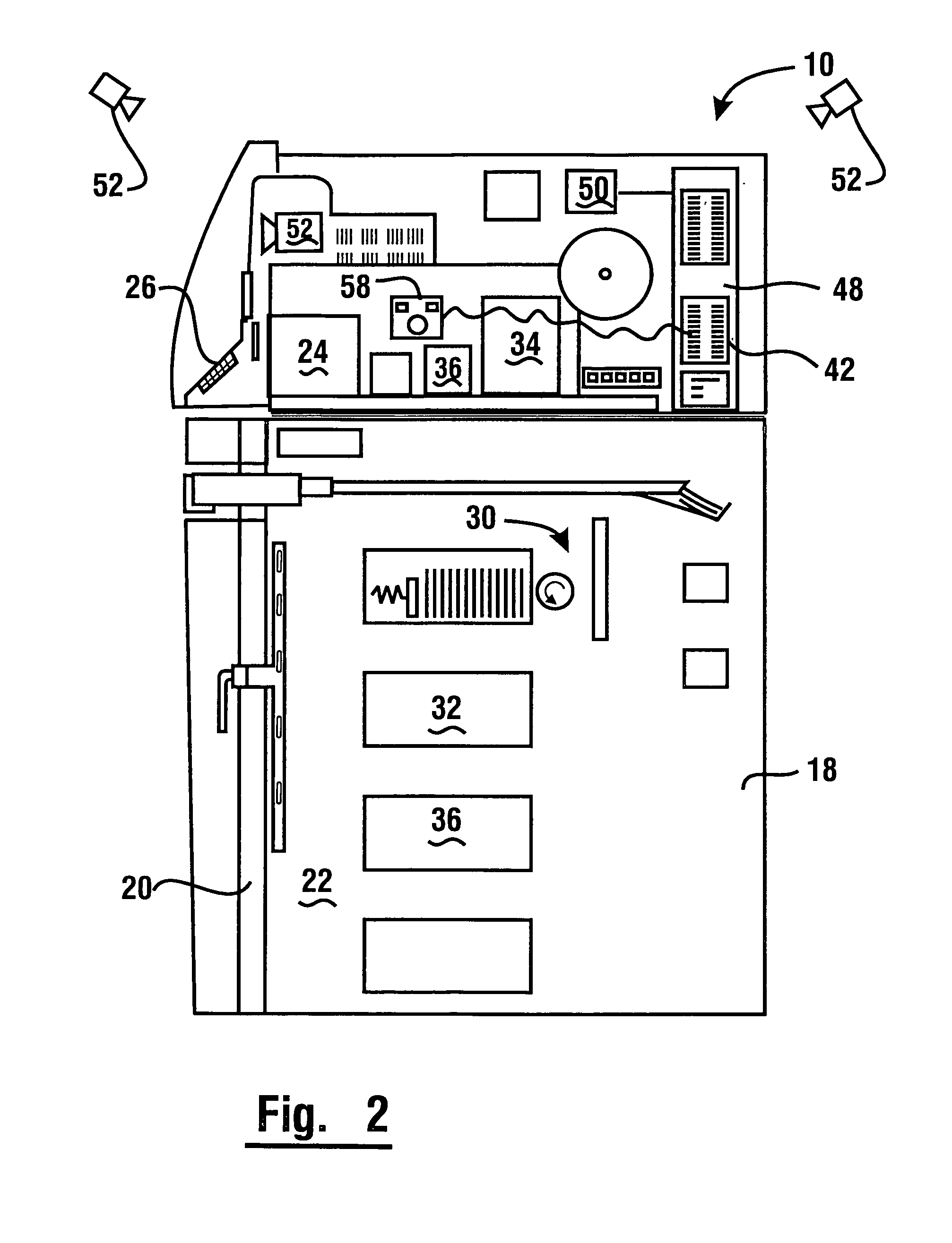
[0011]The foregoing objects are accomplished in one exemplary embodiment by an apparatus including a cash dispensing automated banking machine that includes a visual display, at least one serviceable component, and a controller. For purposes of this disclosure a controller shall be construed as a processor that executes program instructions. The exemplary apparatus also includes a movable image capture device such as a camera in operative connection with the controller, which can be selectively positioned toward and away from the serviceable component. The movable image capture device may be connected to the controller through a universal serial bus (USB) connection. The connection cable may have sufficient length and flexibility to enable the image capture device to be moved to place in its field of view, regions within and outside the machine housing. Visual images generated by the image capture device can be output on the visual display. Thus, regions of the serviceable component that cannot be directly viewed by a servicer by looking into the interior of the machine may be indirectly viewed by a servicer. Exemplary banking machines may include additional image capture devices mounted in fixed or movable relationship relative the banking machine housing which are able to provide visual images of areas in or around the machine.
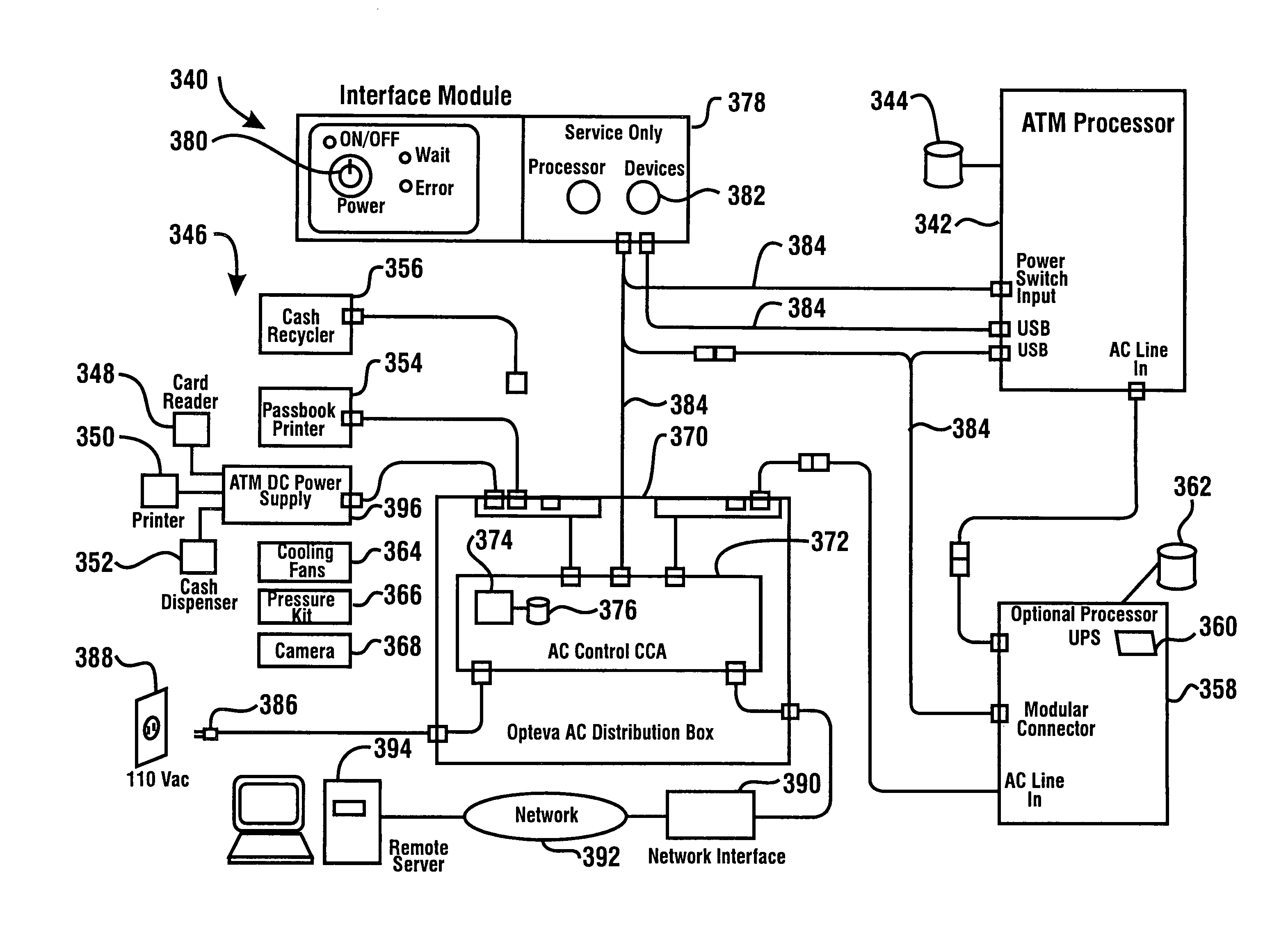
[0016]In some exemplary embodiments an automated banking machine includes components that control the supply of power to devices in the machine. In exemplary embodiments the devices operate to control the supply and shutoff of electrical power to components of the machine in predetermined sequences. In exemplary embodiments predetermined sequences are operative to avoid the risk of damage that may result from electrical power being shut off to devices at undesirable times in the operating sequence. Further exemplary embodiments control the start and shutdown of the terminal processor of the machine. In still other embodiments the shutdown and restart of the terminal processor and other devices in the machine may be controlled remotely. This can facilitate correcting malfunctions that can be remedied merely by shutting down the machine and restarting the terminal processor and other devices.
[0017]In still other embodiments reliability of an automated banking machine can be increased by assuring that configuration files and other information included in a database that operates in connection with a terminal processor of the machine can be recovered in the event of a malfunction. In exemplary embodiments, database software instructions are executed to cause at least one operation of the machine. An initial copy of the database instructions is stored in at least one data store. This original or “embryo” copy is maintained in the data store concurrently with the database software instructions.

Problems solved by technology

Exception instructions may cause the machine to carry out activities that are designed to inform personnel of the theft and / or deter such theft activities.
Such received signals may cause the execution of certain exception instructions.

Method used


Image

  • Automated banking system controlled responsive to data bearing records
  • Automated banking system controlled responsive to data bearing records
  • Automated banking system controlled responsive to data bearing records

Examples


Embodiment Construction

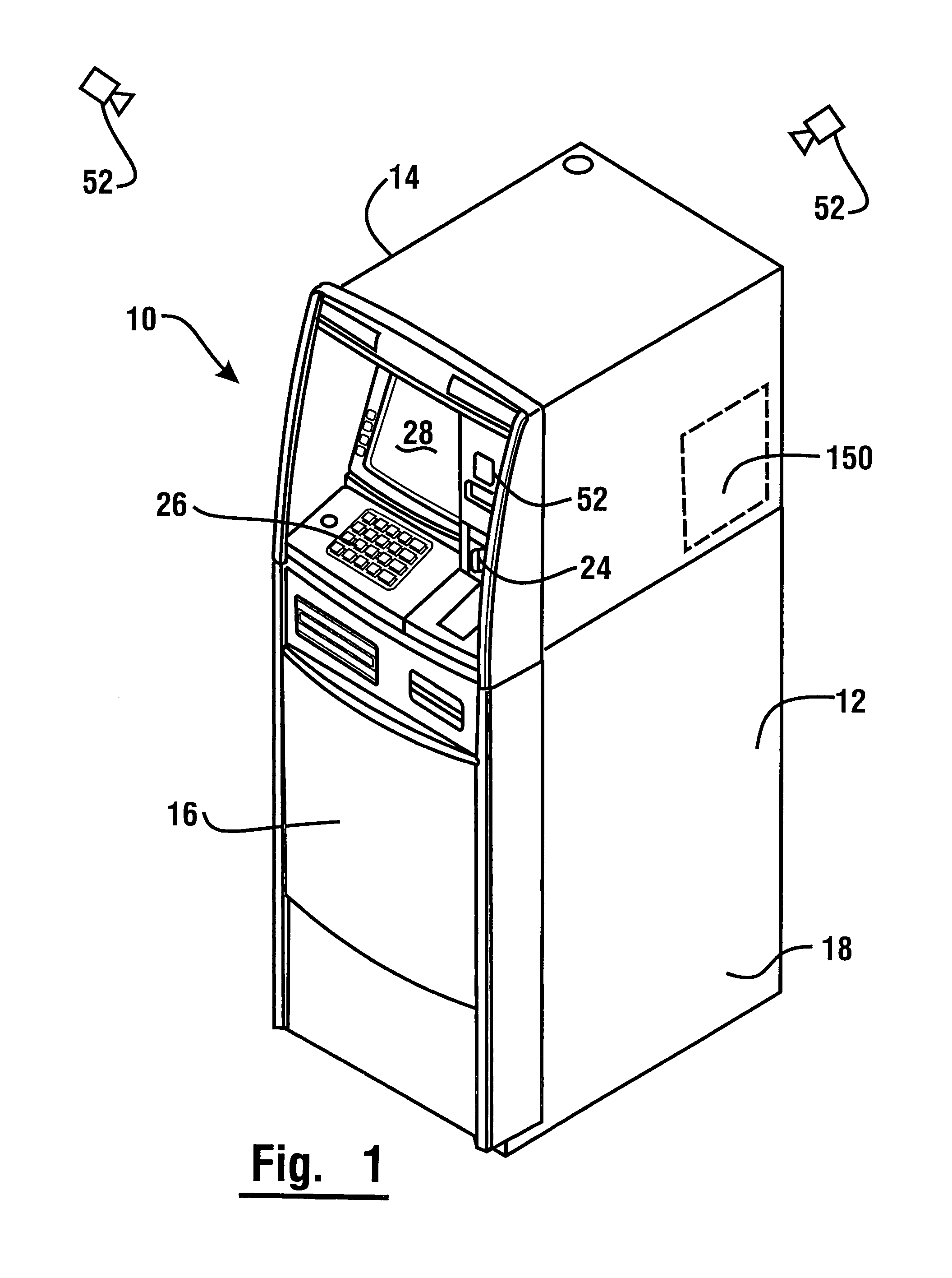
[0039]Referring now to the drawings and particularly to FIG. 1 there is shown therein an exemplary embodiment of an automated banking machine that operates to cause financial transfers using information read from data bearing records in the form of user cards generally indicated 10. In the exemplary embodiment automated banking machine 10 is an ATM, however the features described and claimed herein are not limited to any particular type of automated banking machine. The exemplary ATM includes a housing 12. In the embodiment shown, housing 12 includes an upper housing area 14 and a lower housing area 16 including a secure chest portion 18. Access to an interior area of the chest portion 18 is controlled by a chest door 20 (see FIG. 2) which when unlocked by authorized persons, enables gaining access to the interior area 22 of the chest area. In an exemplary embodiment, access to the upper housing area 14 may be made through an appropriate opening in the housing 12. The opening to the...


PUM


Abstract

An automatic banking machine operates responsive to data bearing records. The machine includes a card reader for reading user cards, and at least one of a note acceptor and a cash dispenser. The automated banking machine carries out financial transfers related to user accounts based on information read from cards. The automated banking machine provides a printed receipt for transactions conducted. The machine carries out transactions when operatively connected to a source of power and a transaction network. The machine also carries out functions to control the power status of devices in the machine.

Description

CROSS REFERENCE TO RELATED APPLICATIONS[0001]This application is a continuation of U.S. application Ser. No. 12 / 459,187 filed Jun. 26, 2009, which claims benefit pursuant to 35 U.S.C. §119(e) of U.S. Provisional Applications 61 / 192,282 filed Sep. 17, 2008; 61 / 133,477 filed Jun. 30, 2008; and 61 / 133,346 filed Jun. 27, 2008, the disclosures of each of which are incorporated herein by reference in their entirety.TECHNICAL FIELD[0002]This invention relates to banking systems controlled by data bearing records that may be classified in U.S. Class 235, Subclass 379.BACKGROUND ART[0003]Automated banking machines may include a card reader that operates to read data from a bearer record such as a user card. The automated banking machine may operate to cause the data read from the card to be compared with other computer stored data related to the bearer. The machine operates in response to the comparison determining that the bearer is a system user authorized to carry out at least one transac...

Claims


Application Information

Patent Timeline
Patent Type & Authority Patents(United States)
IPC IPC(8): G06K5/00G06F17/00G06F1/00G06Q40/00
CPCG06Q20/1085G06Q40/02G07F19/20G07F19/201G07F19/202B65H7/02B65H7/20B65H29/20G07G5/00G07F19/205
Inventor JENKINS, RANDALL W.OWENS, VINCENT L.FOCKLER, GREGORYCOX, JERRYERTLE, TOMKRZIC, DAVESHEPLEY, STEVENBILLETT, NICKCOGAN, VICTOR A.MILLER, WILLISRYAN, MIKE R.CREWS, TIMRAMACHANDRAN, NATARAJAN
Owner DIEBOLD SELF SERVICE SYST DIV OF DIEBOLD NIXDORF INC
Learn More