
Automated Banking System Controlled Responsive to Data Bearing Records

Active Publication Date: 2012-06-07
DIEBOLD SELF SERVICE SYST DIV OF DIEBOLD NIXDORF INC
View PDF3 Cites 32 Cited by
  • Summary
  • Abstract
  • Description
  • Claims
  • Application Information

AI Technical Summary

Benefits of technology

[0008]It is another object of exemplary embodiments to provide an automated banking machine having improved operating and servicing capabilities.
[0009]It is a further object of exemplary embodiments to provide an automated banking machine that deters the theft thereof.
[0010]It is a further object of exemplary embodiments to provide an automated banking machine that can carry out certain computer executable instructions when the machine has been disconnected from its power source and / or network connections.
[0012]It is a further object of exemplary embodiments to provide an automated banking machine that is more energy efficient.
[0018]In some exemplary embodiments an automated banking machine includes components that control the supply of power to devices in the machine. In exemplary embodiments the devices operate to control the supply and shutoff of electrical power to components of the machine in predetermined sequences. In exemplary embodiments predetermined sequences are operative to avoid the risk of damage that may result from electrical power being shut off to devices at undesirable times in the operating sequence. Further exemplary embodiments control the start and shutdown of the terminal processor of the machine. In still other embodiments the shutdown and restart of the terminal processor and other devices in the machine may be controlled remotely. This can facilitate correcting malfunctions that can be remedied merely by shutting down the machine and restarting the terminal processor and other devices.
[0020]In still other exemplary embodiments reliability of an automated banking machine can be increased by assuring that configuration files and other information included in a database that operates in connection with a terminal processor of the machine can be recovered in the event of a malfunction.

Problems solved by technology

Such received signals may cause the execution of certain exception instructions.

Method used


Image

  • Automated Banking System Controlled Responsive to Data Bearing Records
  • Automated Banking System Controlled Responsive to Data Bearing Records
  • Automated Banking System Controlled Responsive to Data Bearing Records

Examples


Embodiment Construction

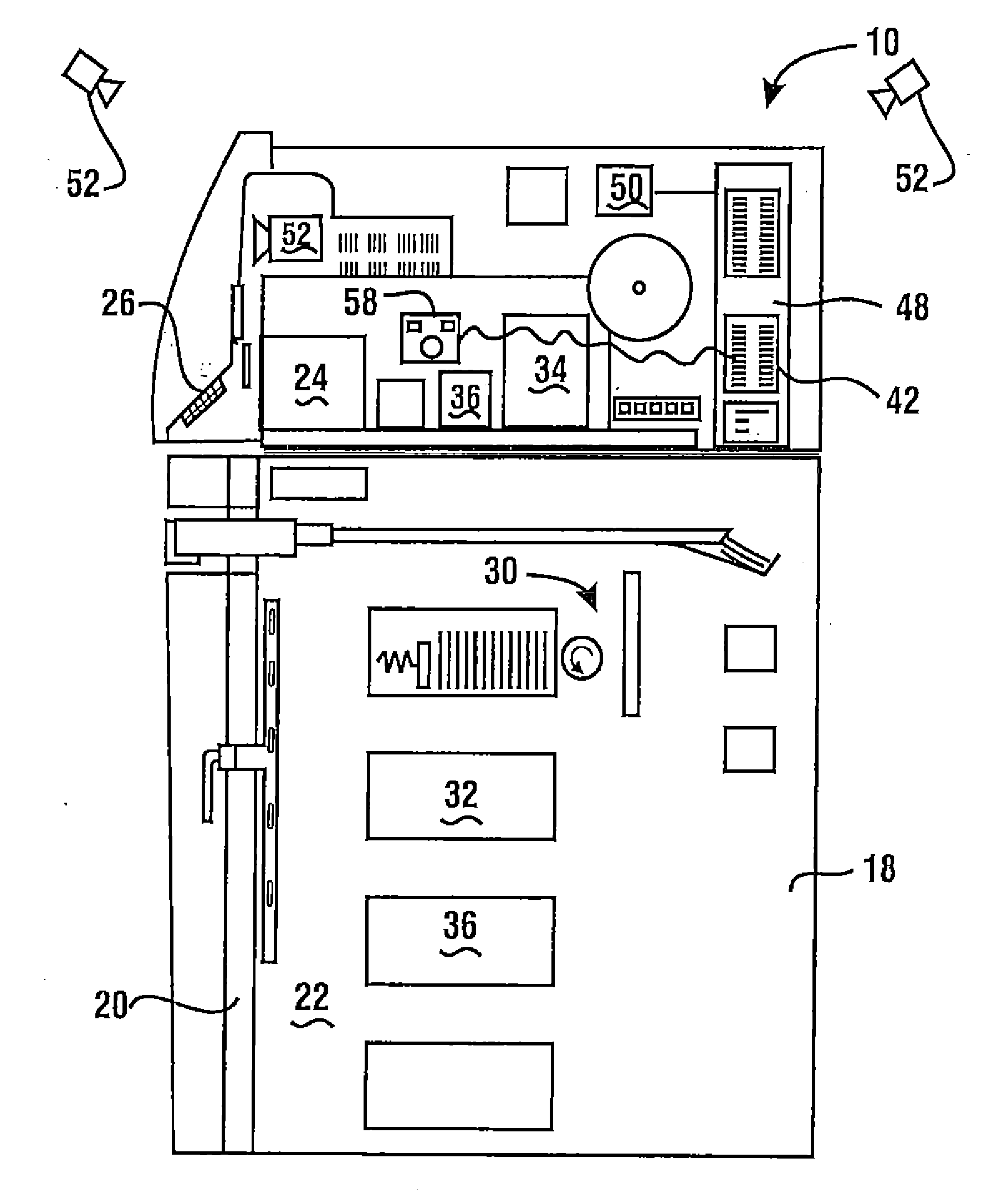
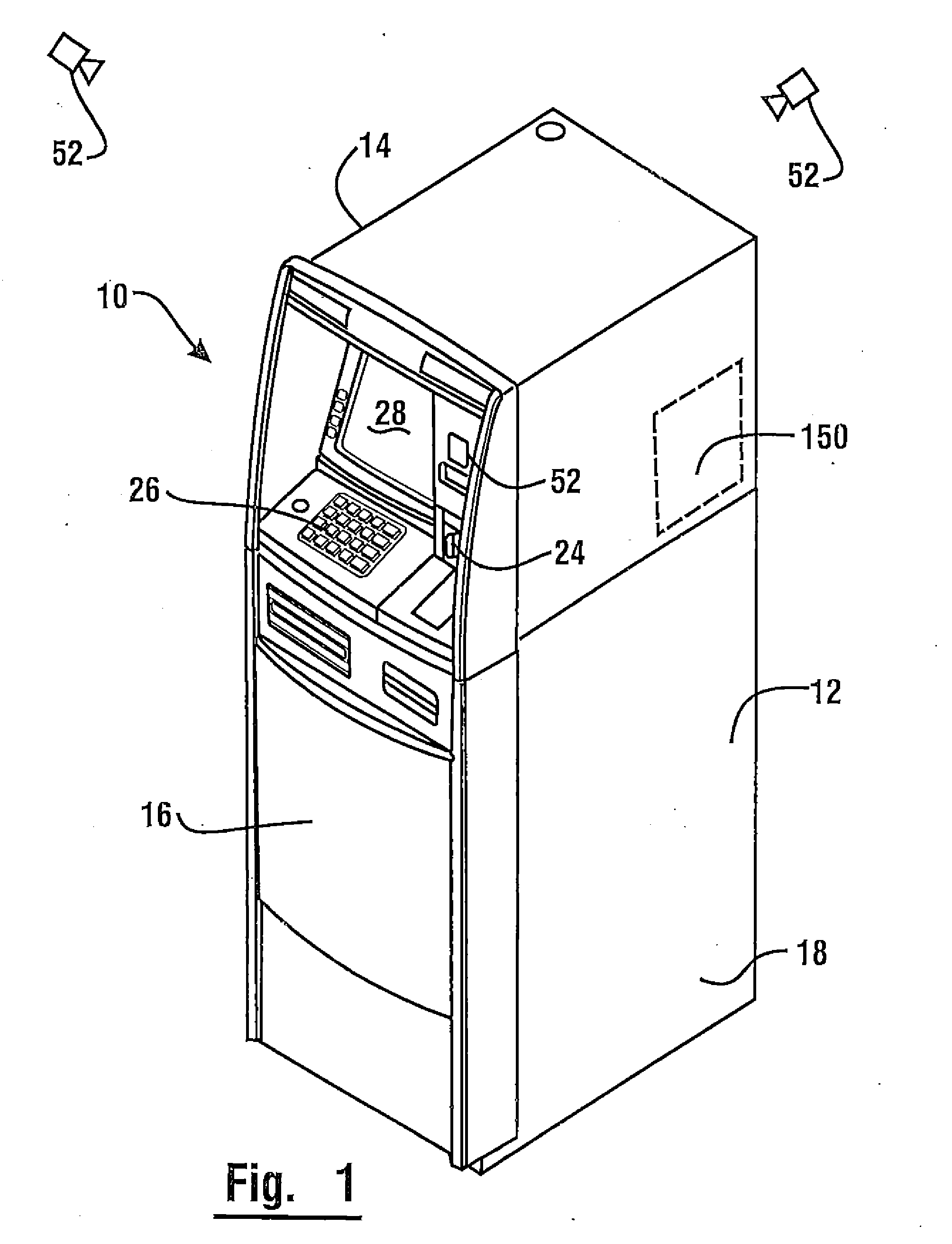
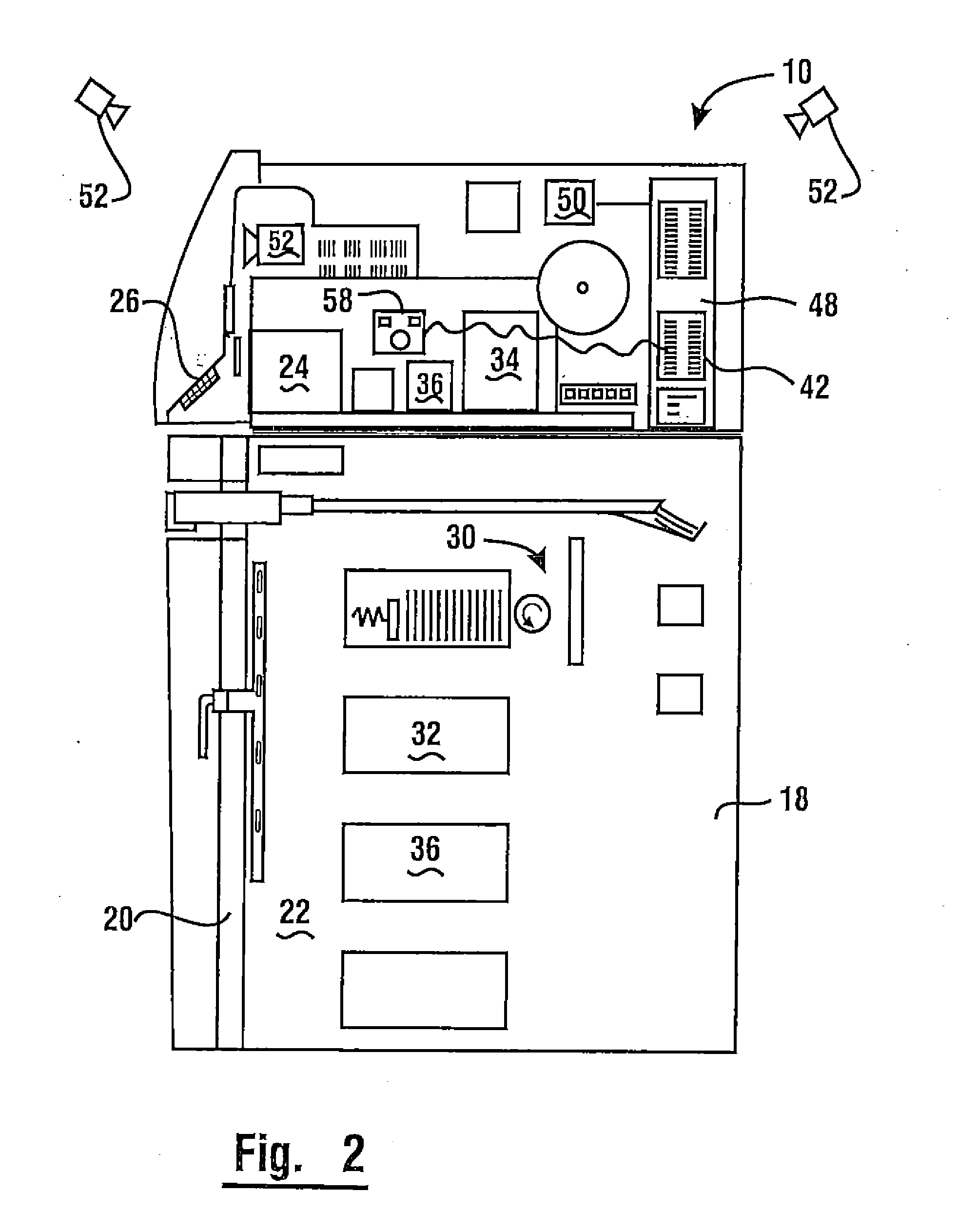
[0045]Referring now to the drawings and particularly to FIG. 1 there is shown therein an exemplary embodiment of an automated banking machine that operates to cause financial transfers using information read from data bearing records in the form of user cards generally indicated 10. In the exemplary embodiment automated banking machine 10 is an ATM, however the features described and claimed herein are not limited to any particular type of automated banking machine. The exemplary machine includes a housing 12. In the embodiment shown, housing 12 includes an upper housing area 14 and a lower housing area 16 including a secure chest portion 18. Access to an interior area of the chest portion 18 is controlled by a chest door 20 (see FIG. 2) which when unlocked by authorized persons, enables gaining access to the interior area 22 of the chest area. In an exemplary embodiment, access to the upper housing area 14 may be made through an appropriate opening in the housing 12. The opening to...


PUM


Abstract

An automatic banking machine operates responsive to data read from data bearing records corresponding to authorized user or financial account data. The machine includes a card reader for reading data from user cards. The automated banking machine causes financial transfers related to financial accounts that correspond to data read from user cards. The automated banking machine also includes devices that control the supply of power to included devices to avoid exceeding power supply capacity.

Description

CROSS REFERENCE TO RELATED APPLICATIONS[0001]This application claims benefit pursuant to 35 U.S.C. §119(e) of Provisional Application 61 / 459,593 filed Dec. 14, 2010 and Provisional Application 61 / 572,328 filed Jul. 14, 2011.[0002]This application is a continuation-in-part of application Ser. No. 13 / 134,592 filed Jun. 10, 2011; Ser. No. 13 / 134,592 is a continuation of Ser. No. 12 / 459,187 filed Jun. 9, 2010. Application Ser. No. 12 / 459,187 claims benefit pursuant to 35 U.S.C. §119(e) of Provisional Applications 61 / 192,282 filed Sep. 17, 2008, 61 / 133,477 filed Jun. 30, 2008 and 61 / 133,346 filed Jun. 27, 2008. The disclosures of each of these applications are incorporated herein by reference in their entirety.TECHNICAL FIELD[0003]This invention relates to banking systems controlled by data bearing records that may be classified in U.S. Class 235, Subclass 379.BACKGROUND ART[0004]Automated banking machines may include a card reader that operates to read data from a bearer record such as ...

Claims


Application Information

Patent Timeline
IPC IPC(8): G07F19/00
CPCG07F19/207G07F19/209G06F1/32Y10S902/08G06Q20/1085G07F19/20G06F1/3293G07F19/206Y02D10/00
Inventor MA, SONGTAOTOEPKE, ERICRYAN, MIKE R.JENKINS, RANDALL W.RAMACHANDRAN, NATARAJANERTLE, THOMAS D.CREWS, TIMMILLER, WILLISBILLETT, NICKSHEPLEY, STEVENKRZIC, DAVECOGAN, VICTOR A.
Owner DIEBOLD SELF SERVICE SYST DIV OF DIEBOLD NIXDORF INC
Learn More