Real-time visual alert display

a visual alert and real-time technology, applied in the field of real-time risk alert systems, can solve problems such as insufficient maturity of technology

Active Publication Date: 2013-06-04
RGT UNIV OF MICHIGAN
View PDF33 Cites 12 Cited by
  • Summary
  • Abstract
  • Description
  • Claims
  • Application Information

AI Technical Summary

Benefits of technology

[0009]Finally, in some embodiments, the display system of the present teachings can provide pop-up alerts, or other alerts, when a combination of events occurs which produces a situation where there could be a possible important physiologic abnormality that could potentially cause risk or harm to the patient.

Problems solved by technology

Initial efforts in producing an electronic anesthesia information system (known as AIMS) started in the 1980s; the technology was not mature and not widely adopted until relatively recently.

Method used


Image

  • Real-time visual alert display
  • Real-time visual alert display
  • Real-time visual alert display

Examples


Embodiment Construction

[0025]Example embodiments will now be described more fully with reference to the accompanying drawings.

General Layout of Screen.

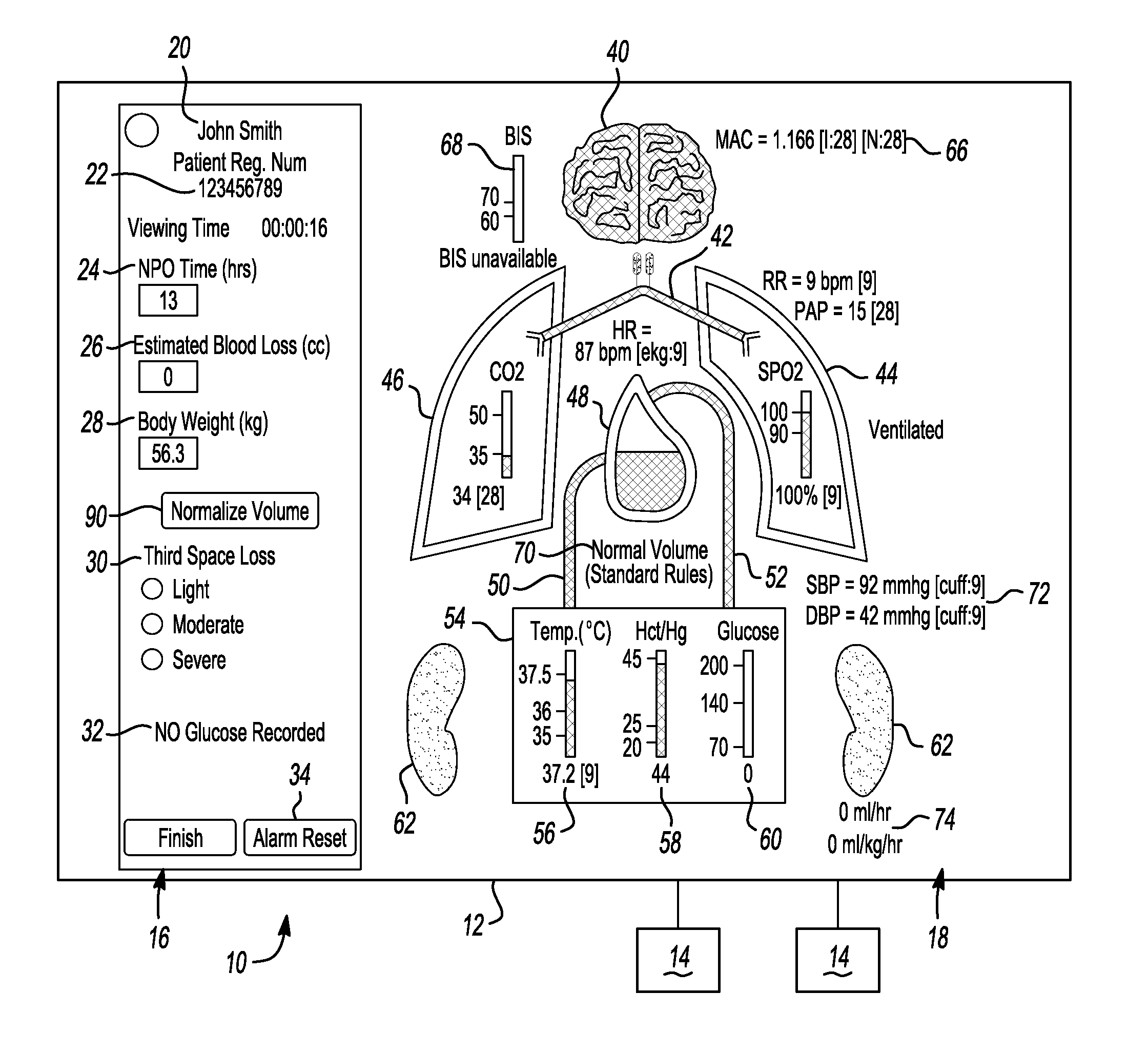
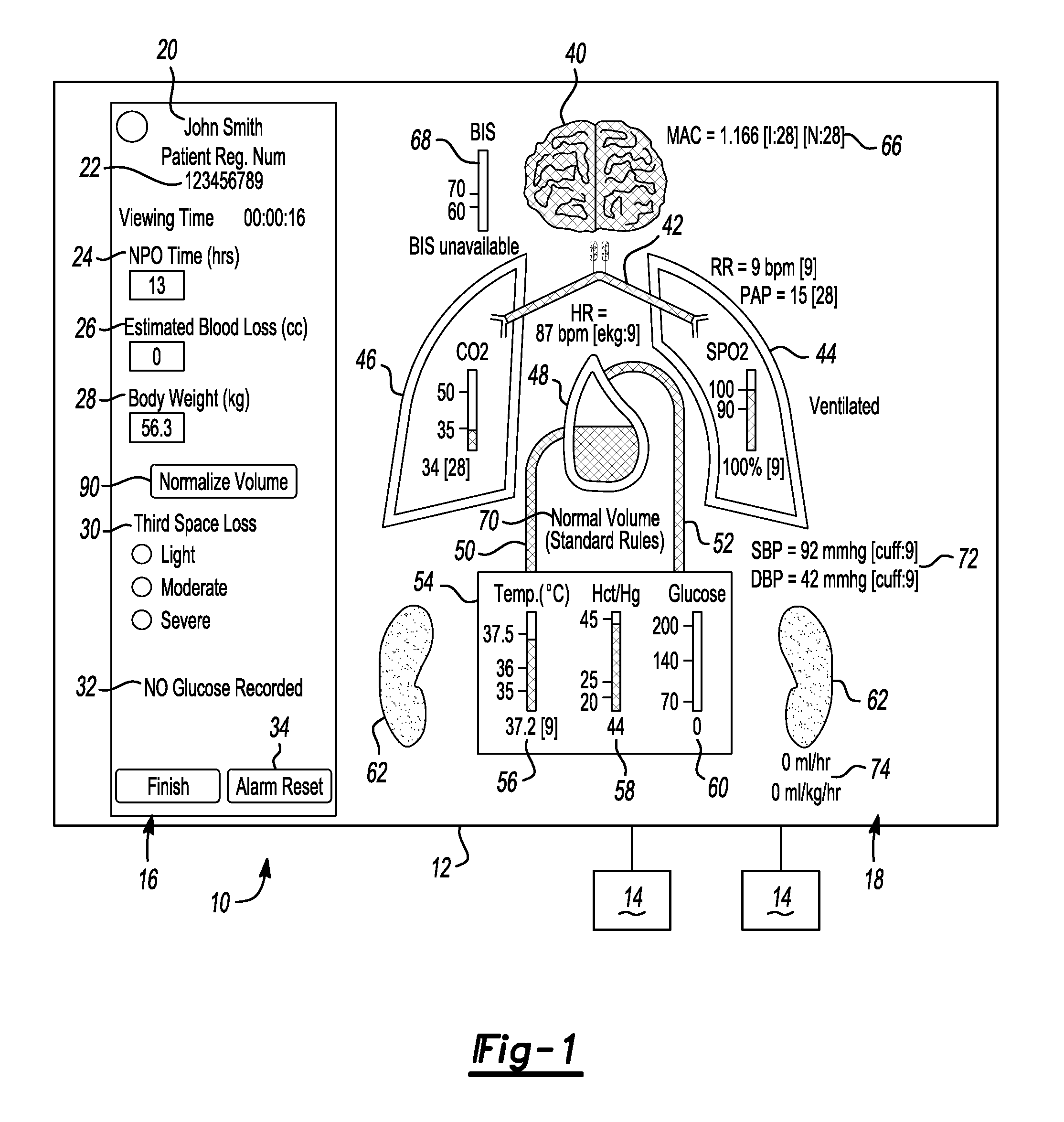
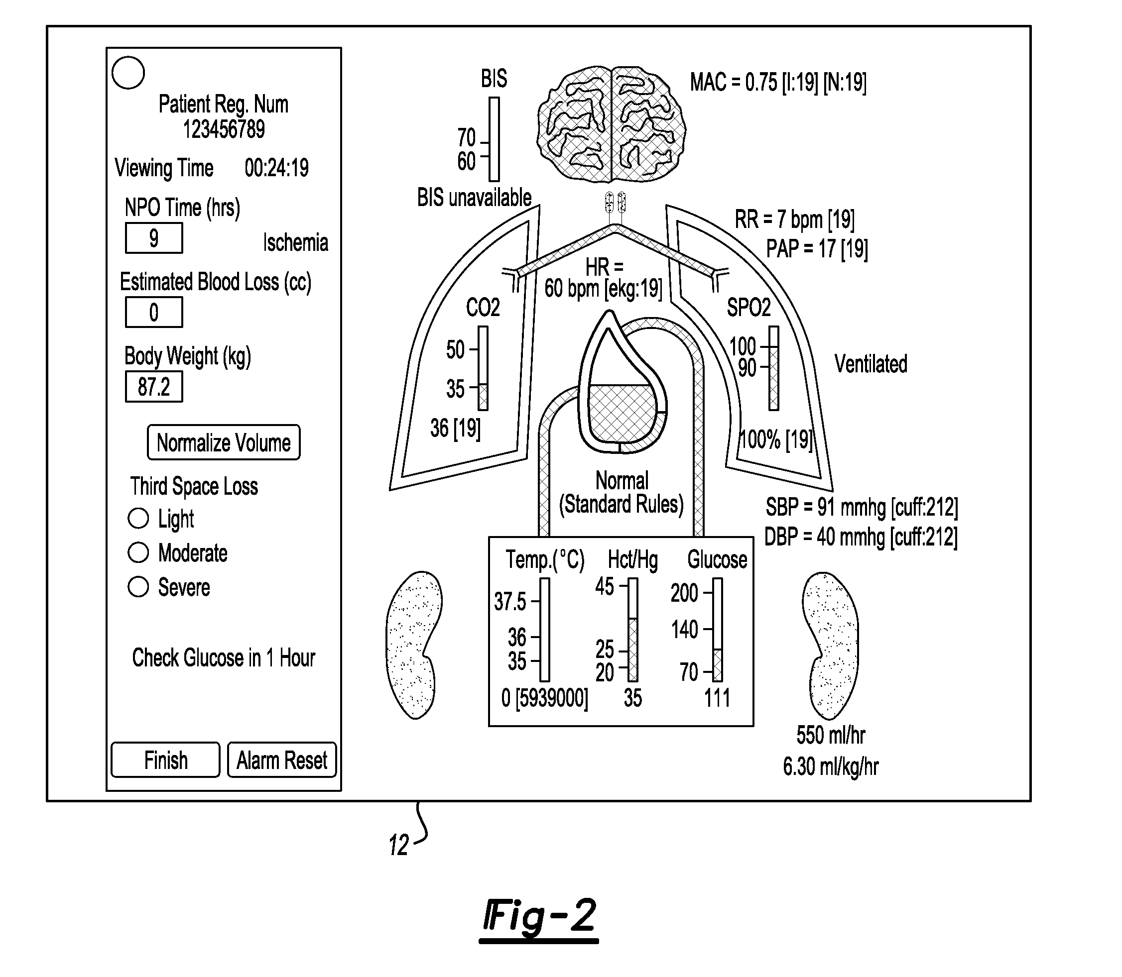
[0026]According to the principles of the present teachings, as illustrated in FIGS. 1-8, a real-time visual alert display system 10 is provided. The real-time visual alert display system 10 can comprise an alert display device 12 operably coupled to a plurality of sensors, probes, or other data collecting or monitoring devices 14. The plurality of sensors 14 can be operable to be coupled to a patient and collect real-time physiologic data from the patient. Alert display device 12 can comprise a control system or controller separate from or integrated therewith for assembling data from the plurality of sensors 14 for interpretation and / or display on alert display device 12, which will be described herein. It should be noted that alert display device 12 can comprise one or more display layouts, however, generally, in some embodiments the alert display 10 comp...


PUM


Abstract

An alert system for patient treatment that incorporates patient data to display information in readily identifiable icons for vital organs, and in a useable, real-time, updated fashion that extracts data from the medical history, the current medical management, and the current physiologic monitors to produce warnings and alerts to enable practitioners to be made aware of physiologic systems at risk, (physiologic systems in normal range, borderline normal range, and abnormal range of function). These data are not only presented, but also use real-time queries and calculations to enable practitioners to have the types of data that would traditionally assist them in patient care but only be available by reviewing the medical literature and / or doing retrospective individual calculations while providing patient care.

Description

CROSS-REFERENCE TO RELATED APPLICATIONS[0001]This application claims the benefit of U.S. Provisional Application No. 61 / 249,801, filed on Oct. 8, 2009 and U.S. Provisional Application No. 61 / 295,829, filed on Jan. 18, 2010. The entire disclosures of each of the above applications is incorporated herein by reference.FIELD[0002]The present disclosure relates to risk alert systems and, more particularly, relates to real-time risk alert systems capable of extracting data from medical history, current medical management, and / or current physiological monitors and providing real-time alerts related thereto.BACKGROUND AND SUMMARY[0003]This section provides background information related to the present disclosure which is not necessarily prior art. This section also provides a general summary of the disclosure, and is not a comprehensive disclosure of its full scope or all of its features.[0004]The opportunity for this new unique type of medical alert system has been brought about by the exp...

Claims


Application Information

Patent Timeline
Patent Type & Authority Patents(United States)
IPC IPC(8): A61B5/00A61B5/0205
CPCA61B5/7435A61B5/4821A61B5/743G06F19/3406A61B5/02055A61B5/7275A61B5/029A61B2560/0276A61B5/7445G16H40/63
Inventor TREMPER, KEVIN K.BLUM, JAMES M.
Owner RGT UNIV OF MICHIGAN
Why Eureka
Try Eureka