
Beater bracket and variable drive lever system with variable pivot point spring rotor for bass drum foot pedals

a technology of variable pivot point spring rotor and foot pedal, which is applied in the field of foot pedals, can solve the problems of inability to optimize the impact force of the beater bracket 04, in itself, and high production cost, and achieves the effect of simple and economical production, easy adjustment, and maximum impact of the beater against the bass drum

Active Publication Date: 2013-06-04
AXIS PEDAL & DRUM CO INC
View PDF34 Cites 37 Cited by
  • Summary
  • Abstract
  • Description
  • Claims
  • Application Information

AI Technical Summary

Benefits of technology

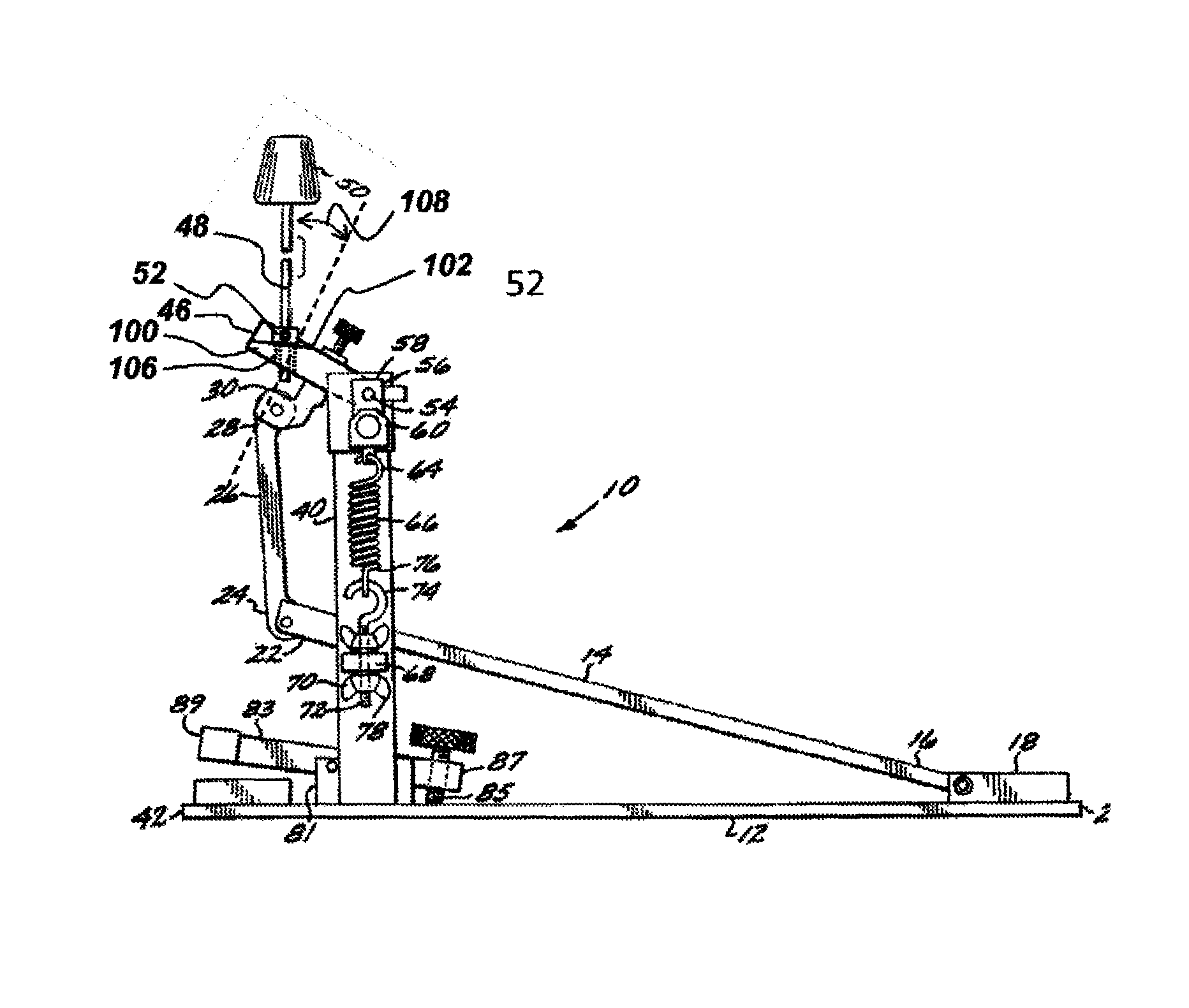
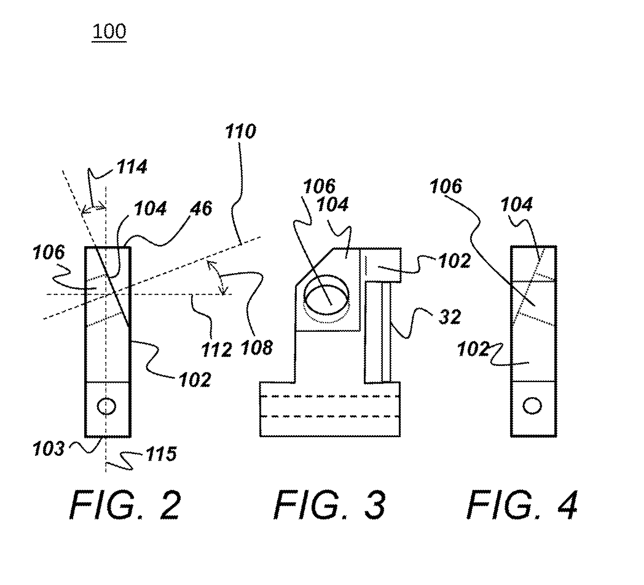
[0009]The present invention provides an improved bass drum pedal which has a variable drive action which is simple and economical to produce and which is readily adjustable to accommodate a wide variety of foot strengths. Importantly, the present invention includes a new beater bracket that is formed with a mounting surface that tips a beater shaft forward to create a forward beater angle that maximizes the beater impact against a bass drum.

Problems solved by technology

Unfortunately, some drummers have a “heavier foot” than others and, hence, must constantly guard against causing the beater to strike the drum head too vigorously, while other drummers have a very “light foot” and, consequently, must exert conscious effort to effect a desired beater impact.
However, the adjustable drive action foot pedals of the prior art have been complex, expensive to produce and difficult to adjust and maintain.
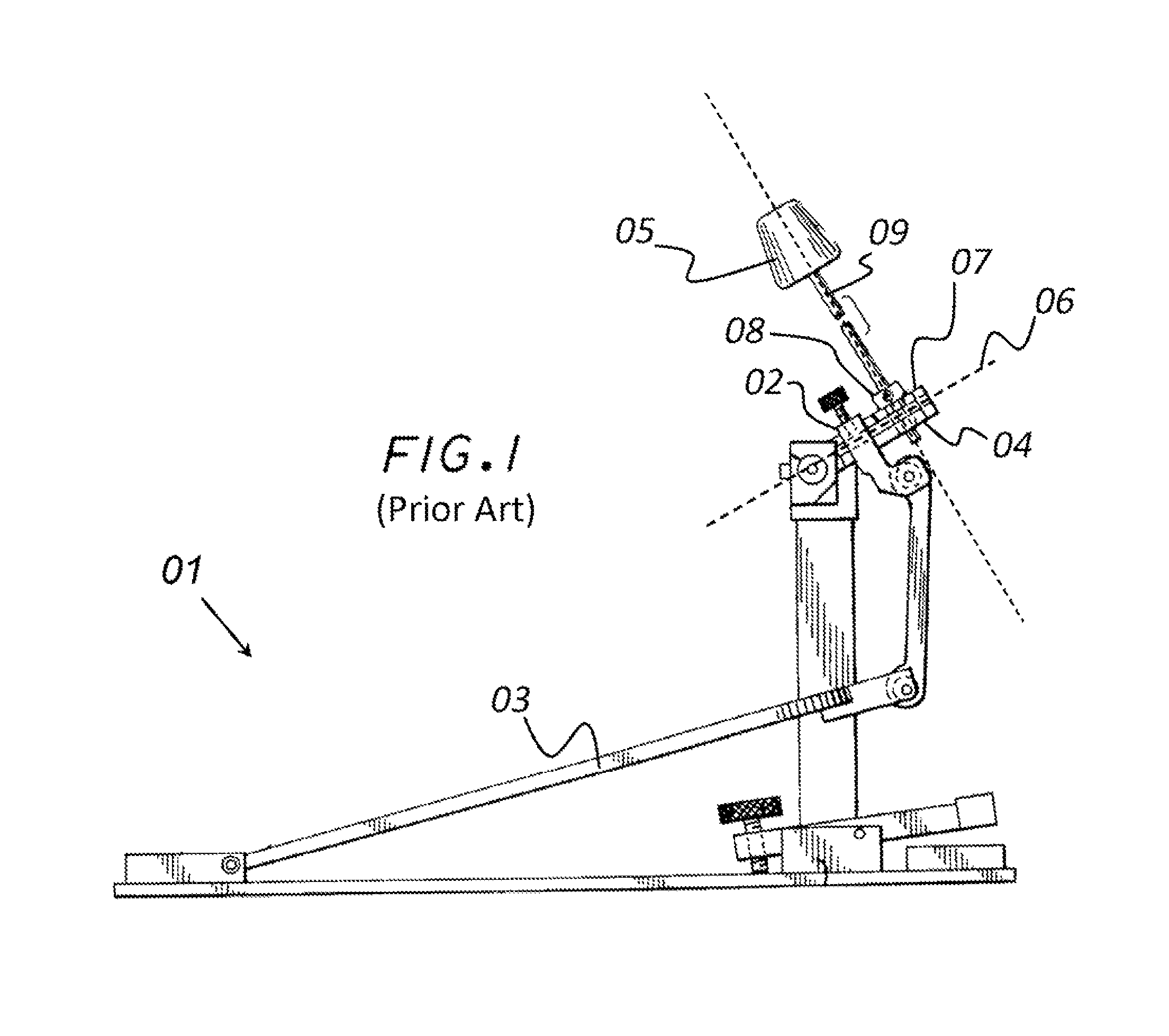
While the '592 patent describes a very desirable product that provides for a wide range of adjustability of optimizing performance, the beater bracket 04, in of itself, does not optimize impact force.
This configuration, in of itself, does not optimize the impact force of the beater 05.

Method used


Image

  • Beater bracket and variable drive lever system with variable pivot point spring rotor for bass drum foot pedals
  • Beater bracket and variable drive lever system with variable pivot point spring rotor for bass drum foot pedals
  • Beater bracket and variable drive lever system with variable pivot point spring rotor for bass drum foot pedals

Examples


Embodiment Construction

[0035]The following description is presented to enable one of ordinary skill in the art to make and use the invention and to incorporate it in the context of particular applications. Various modifications, as well as a variety of uses in different applications will be readily apparent to those skilled in the art, and the general principles defined herein may be applied to a wide range of embodiments. Thus, the present invention is not intended to be limited to the embodiments presented, but is to be accorded the widest scope consistent with the principles and novel features disclosed herein.

[0036]In the following detailed description, numerous specific details are set forth in order to provide a more thorough understanding of the present invention. However, it will be apparent to one skilled in the art that the present invention may be practiced without necessarily being limited to these specific details. In other instances, well-known structures and devices are shown in block diagr...


PUM


Abstract

Described is a bass drum foot pedal having a variable drive lever linkage with variable arc ratios connecting the foot pedal to a beater bracket. The beater bracket is formed with a mounting surface that tips a beater shaft forward to create a forward beater angle that maximizes the beater impact against a bass drum.

Description

PRIORITY CLAIM[0001]This is a non-provisional application of U.S. Provisional Application No. 61 / 420,851, filed on Dec. 8, 2010, entitled, “A21 Beater Bracket and Variable Drive Lever System with Variable Pivot Point Spring Rotor for Bass Drum Foot Pedals.”BACKGROUND OF THE INVENTION[0002](1) Field of Invention[0003]This invention relates to foot pedals for bass drums and, more specifically, to a beater bracket that is designed to accelerate a beater into the bass drum with greater force and velocity.[0004](2) Description of Related Art[0005]Foot pedals have long been used for striking bass drums, since the use of a foot pedal frees both of the drummer's hands for use with snare drums, cymbals or other devices. However, most prior art bass drum pedals have been constructed with a fixed drive action. This means that the drummer must vary the force with which the beater impacts the drum head by varying the force applied by the drummer's foot. Unfortunately, some drummers have a “heavi...

Claims


Application Information

Patent Timeline
Patent Type & Authority Patents(United States)
IPC IPC(8): G10D13/02
CPCG10D13/006G10D13/11
Inventor JOHNSTON, DARRELLBLASHAW, CHARLES
Owner AXIS PEDAL & DRUM CO INC
Learn More