Pressure container

a technology of pressure container and pressure chamber, which is applied in the direction of liquid transfer devices, pliable tubular containers, instruments, etc., can solve the problems of tightness problems, creaking or crumpling spots, and becoming more and more rigid or imbedded, etc., to achieve simple and economical production and favorable manufacture of canisters

Inactive Publication Date: 2005-04-05
HILTI AG
View PDF2 Cites 11 Cited by
  • Summary
  • Abstract
  • Description
  • Claims
  • Application Information

AI Technical Summary

Benefits of technology

Advantageously, if the compensation chamber is freely moveable; in other words, in the form of a pillow made of laminated film or foil, and arranged in the inner container, the configuration of the compensation chamber according to the invention as a freely moveable pillow has the advantage that a pressure container or canister provided with such a pillow is simple and economical to produce. The cushion can be introduced into the inner container prior to sealing the pressure container, whereby the cushion or the compensation chamber is previously filled with the compressible medium. After filling of the inner container with fill material, the compressed medium, for example air, can then be compressed to a fraction of its original volume. A freely moveable compensation body made out of a foam, for example, could similarly be provided.
Simultaneously, the compensation chamber or the compensation body could be arranged around the fill material chamber so that the compensation chamber or compensation body is separated outwardly via the metal bag or the metal foil of the propellant chamber and shielded in a medium tight fashion. For realization of this embodiment only a plastic bag, in particular made of a composite or laminated foil or another expandable / compressible material, needs to be introduced into the metal bag, which forms the fill material chamber. In this instance, again, the advantage resides in the favorable manufacture of the canister or the pressure container according to the invention.
It can be advantageous if the compensation chamber is filled with air, since such medium does not incur any additional manufacturing costs.

Problems solved by technology

Despite the inherent advantageous tightness of this metal bag system pressure container at the connecting seam of the outer container and the inner container according to U.S. Pat. No. 5,069,590, tightness problems can, however, develop as the result of temperature variations.
Because of these undesirable deformation conditions, local creasing or crumpling spots occur on the metallic inner bag, such spots becoming more and more rigid or imbedded due to cold forming.
Consequently, this behavior results in the formation of a hole at the crumpled or crease spot of the inner bag and the pressure container or the canister fails due to leakage.

Method used


Image

  • Pressure container
  • Pressure container
  • Pressure container

Examples


Embodiment Construction

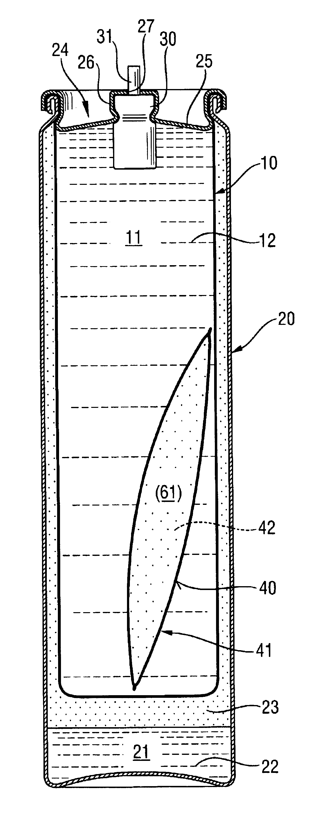
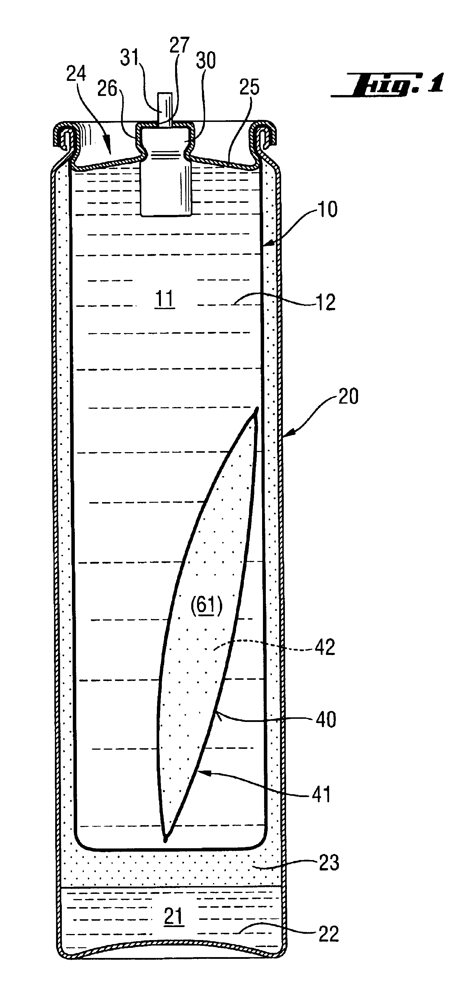
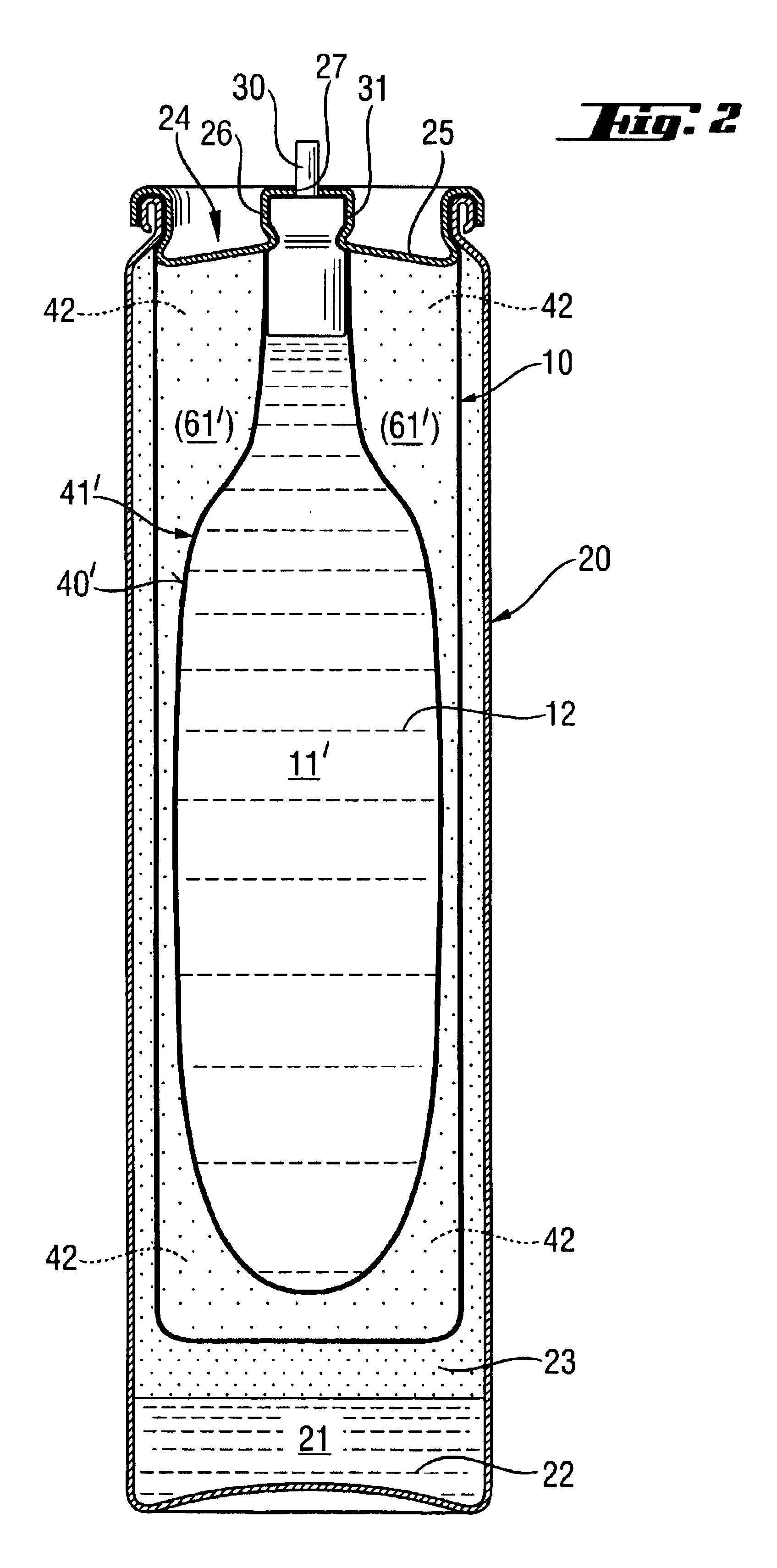
FIG. 1 shows a pressure container according to the invention, formed of an outer container 20 and an inner container 10. The outer container 20 in this embodiment is made of a relatively thick-walled metallic material, for example aluminum, while the inner container 10 is made of a relatively thin-walled, deformable and / or collapsible metallic material, such as thin-walled aluminum, for example. In the area of the upper opening 24, both containers 10, 20 are connected with each other and mutually sealed by rolling. The opening 24 is sealed tight against the pressure container contents leaking to the external environment. The inner container 10 encloses a fill material chamber 11 in which a dispensable fill material 12, for example, a combustible liquid fuel, is contained. Such fill material 12 or liquid fuel is under the pressure of a propellant material 22, 23 contained in the propellant chamber 21 of the outer container. The propellant is in a liquid phase 22 and in a gas phase 23...


PUM


Abstract

A pressure container with an outer container (20) and a constantly deformable or compressible inner container is arranged within the outer container (20), whose container wall is constructed of a metallic foil. A fill material chamber (11) for fill material (12) is arranged in the inner container (10) and in the outer container (20), a propellant chamber (21) is formed for propellant (22, 23), which are separated from one another in a fluid- and/or gas-tight manner. The pressure container is furthermore provided with a cover part (25) for sealing the containers (10, 20), on which a valve part (30) is arranged for dispensing fill material (12) from the fill material chamber (11) to the outside. For improving the pressure container it is proposed that a compensation body (41) be provided in the inner container (10) for the purpose of compensating volume variations in the fill material chamber (11).

Description

BACKGROUND OF THE INVENTIONThe present patent application relates to a pressure container of the type having an outer container enclosing a deformable inner container formed of a metal foil. The inner container forms a chamber for a fill material. The outer container forms a chamber for a propellant. The outer container has a closure part for dispensing the fuel or fill material. Such containers are used in fuel-operated setting tools, wherein they contain the fuel.Liquid hydrocarbons used as the fuel in the setting tools are stored in pressure vessels. The interchangeable pressure containers or fuel canisters are formed with a dispensing or dosing head attached to the fuel canister by means of a snap-on connection. The pressure container / fuel canister and dispensing head are introduced onto the setting tool. The purpose of the system is to continuously maintain the fuel in the liquid phase for dispensing through the dispensing head. Similar arrangements are made also in other appli...

Claims


Application Information

Patent Timeline
Patent Type & Authority Patents(United States)
IPC IPC(8): B65D83/14B65D83/38
CPCB65D83/62
Inventor SCHIESTL, ULRICHGSCHWEND, HANSWOLF, IWANKLIMA, ANDREASGRANACHER, THOMASODONI, WALTERROSENBAUM, ULRICH
Owner HILTI AG
Why Eureka
Try Eureka