Clamping device for a steering column

a technology of a clamping device and a steering column, which is applied in the direction of steering column, steering parts, vehicle components, etc., can solve the problems of high production cost, complicated second disc, and high production cost of the clamping device disclosed in u.s. pat. no. 5,394,767, so as to improve the safety of the driver of the motor vehicle, enhance the operation safety, and ensure the effect of safety

Inactive Publication Date: 2006-09-28
INA SCHAEFFLER KG
View PDF15 Cites 11 Cited by
  • Summary
  • Abstract
  • Description
  • Claims
  • Application Information

AI Technical Summary

Benefits of technology

[0008] Since the first clamping plate element does not have any shaped parts for the rolling body, and can thus for example be formed by a simple punching procedure from a standard metal sheet, it is particularly simple and economical to produce. The clamping device according to an exemplary embodiment of the present invention only comprises one clamping disc in which shaped parts for the rolling body are to be provided. Consequently, the production costs are considerably reduced. Moreover, since no recess for accommodating the rolling body is provided in the first clamping plate, the thickness of the first clamping plate can be minimised, as a result of which the weight of the clamping device according to the present invention is minimised. Moreover, the clamping device according to the present invention comprises only few components and is thus cost-effective to produce and easy to install.
[0015] According to a further exemplary embodiment of the present invention, the clamping device further comprises a tie bolt, arranged at a right angle in relation to the steering column, wherein the steering column is guided between a first supporting arm and a second supporting arm of a fixed bracket. The tie bolt extends between the first and the second supporting arms, with the first end of the tie bolt being held by the first supporting arm. On the second end of the tie bolt, the second clamping plate element is affixed such that it is fixed, i.e. non-slidable, in axial direction of the tie bolt. The first clamping plate element is arranged between the second clamping plate element and the second supporting arm such that the steering column is firmly held between the first and the second supporting arms if the first and the second clamping plate elements are rotated such that they are in the clamped position, and the length and / or position of the steering column between the first supporting arm and the second supporting arm are / is adjustable if the first and the second clamping plate elements are rotated such that they are in the released position. In this way a position adjustment device for a steering column is stated which with relatively simple means makes it possible to clamp and release the length adjustment and height adjustment of a steering column, which position adjustment device comprises fewer components and is lighter in weight while still being able to withstand very considerable clamping forces so that safe clamping of the steering column is ensured. The clamping device can for example be prefabricated as a unit and can be supplied in a preassembled state to motor vehicle manufacturers.

Problems solved by technology

The clamping device disclosed in U.S. Pat. No. 5,394,767 is associated with a disadvantage in that due to the very considerable clamping forces required the first and the second disc necessarily have to be made of metal, and the first and the second disc are complex and expensive to produce since each disc has to comprise recesses which match the balls, for the purpose of guiding the balls.
Therefore, the clamping device disclosed in U.S. Pat. No. 5,394,767 is expensive to produce and moreover very heavy, due to the necessary use of metal as a material for the discs.
As is the case in the device disclosed in U.S. Pat. No. 5,394,767, the clamping device disclosed in US 2002 / 0083784 A1 is also associated with a disadvantage in that due to the very considerable clamping forces needed for clamping a steering column the two discs have to be made of metal.
Since in the device according to US 2002 / 0083784 A1 ball ramps have to be provided in each disc, which ball ramps are complicated to produce, this device too is associated with very considerable production costs.
Furthermore, this device too, due to the use of metal discs which also for the purpose of incorporating the ramps have to have a certain thickness, is very heavy.

Method used


Image

  • Clamping device for a steering column
  • Clamping device for a steering column
  • Clamping device for a steering column

Examples


Embodiment Construction

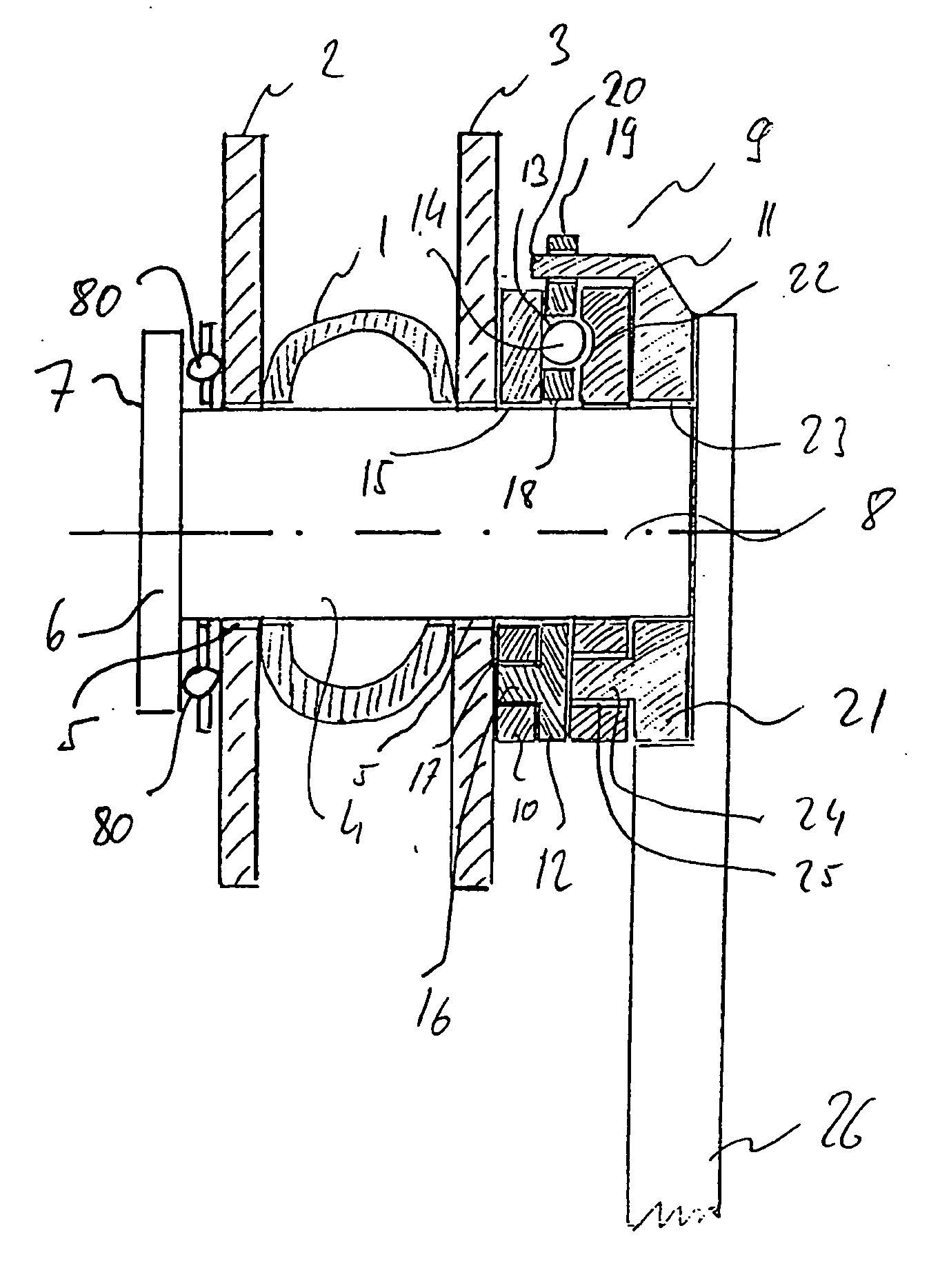
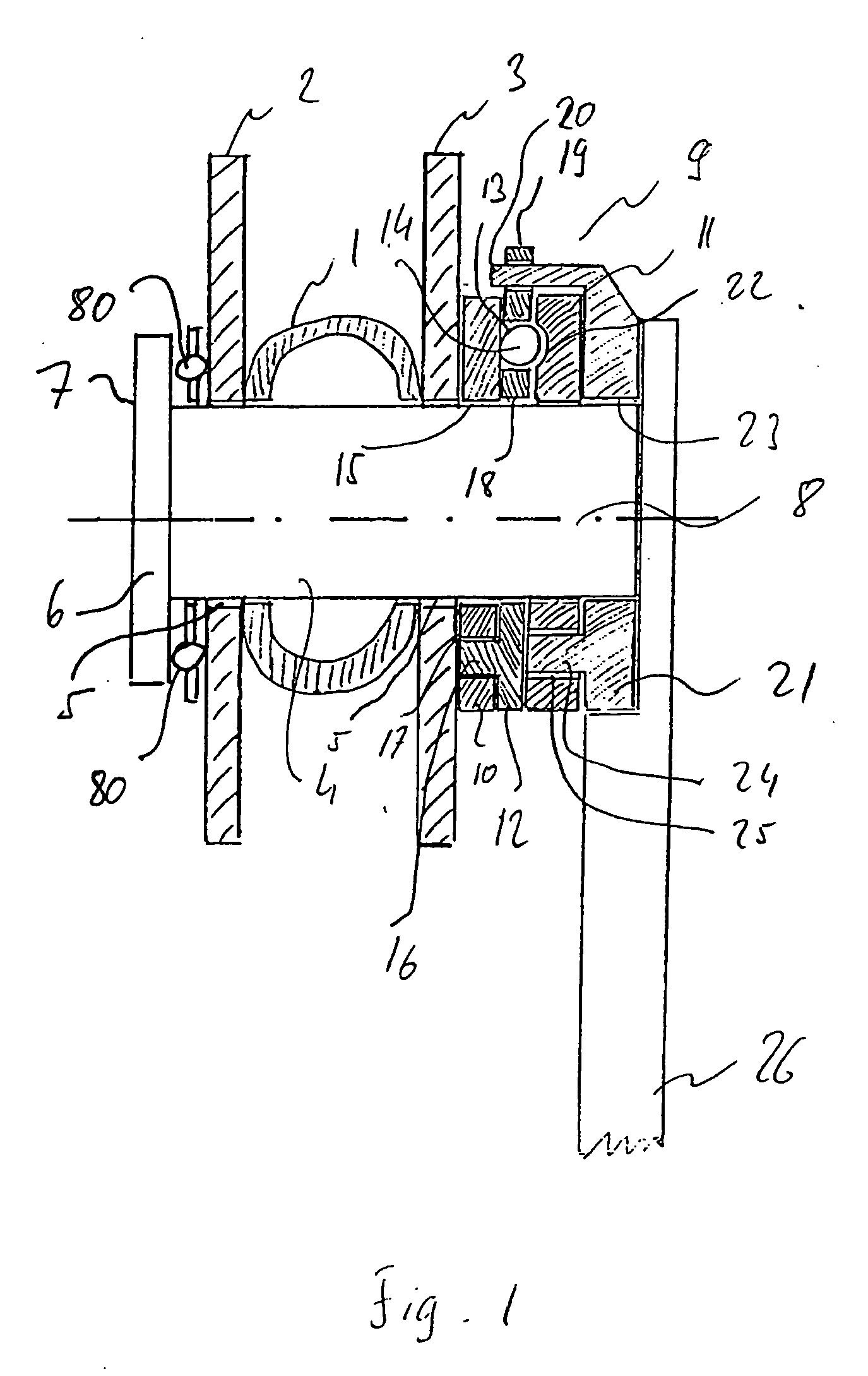
[0021]FIG. 1 shows a position adjusting device for a steering column 1, in particular of a motor vehicle, which position adjusting device is arranged between a first supporting arm 2 and a second supporting arm 3. The supporting arms 2 and 3 form part of a fixed bracket (not shown in FIG. 1) in the region of the instrument panel of a motor vehicle. A tie bolt 4 is provided between the first supporting arm 2 and the second supporting arm 3, which tie bolt 4 is arranged at a right angle in relation to the steering column 1. Preferably the tie bolt 4 is a cylindrical bolt. The tie bolt 4 leads through apertures 5 in the first and second supporting arms 2, 3. For the purpose of attaching the tie bolt 4, on one end 6 of the tie bolt a region 7 is provided where the diameter is larger than the diameter of the aperture or borehole 5 in the supporting arm 2. Through the region with larger diameter 7, the tie bolt 4 is held in axial direction, in FIG. 4 towards the right, to the first suppor...


PUM


Abstract

The application describes a clamping device for a steering column, in which a first clamping plate element is rotatable between a released position and a clamped position in relation to a second clamping plate element, wherein a rolling body which establishes contact is provided between the clamping plate elements. The second clamping plate element comprises a clamping ramp with a contour for the rolling body so that when the clamping plate elements are rotated in relation to each other, the space between the clamping plate elements changes. One clamping plate element comprises a surface which forms a plane on which the rolling body rolls from the released position to the clamped position.

Description

FIELD OF THE INVENTION [0001] The present invention relates to a clamping device for fixing the position of a vehicle steering column which is adjustable in length and / or inclination, in particular a motor vehicle steering column. TECHNOLOGICAL FIELD [0002] Steering column position adjusting devices with which the inclination as well as the length of the steering column can be adjusted, i.e. the position of the steering wheel in relation to the operator is adjustable, are used to improve driving comfort and achieve individual adaptation of the steering wheel position to the requirements of the driver of the vehicle. [0003] Furthermore, steering column position adjusting devices are known with which height adjustment of the steering column is achievable so that it becomes possible for vehicle drivers of different build to optimally adjust the steering wheel to suit their needs and the particular driving situation. These clamping devices not only improve the comfort but also the safet...

Claims


Application Information

Patent Timeline
Patent Type & Authority Applications(United States)
IPC IPC(8): B62D1/18B62D1/184
CPCB62D1/184
Inventor ZERNICKEL, ALEXANDERDIRNBERGER, THOMASHOCHMUTH, HARALDGRIMSMANN, GUIDOKLUEMPER, HANSWILKEN, RAINERSASS, CARSTENKITTLER, HOLGER
Owner INA SCHAEFFLER KG
Why Eureka
Try Eureka