Double-axle, shock-resistant rotation rate sensor with linear and rotary seismic elements

a rotation rate sensor and linear and rotary technology, applied in the direction of acceleration measurement using interia forces, turn-sensitive devices, instruments, etc., can solve the problems of insensitive design, inability to directly excite linear excitations or external rotational excitations, and save control-system complexity, so as to save space, save asic area and current draw or power consumption, and save cost-effective signal processing

Active Publication Date: 2012-08-23
CONTINENTAL TEVES AG & CO OHG
View PDF13 Cites 45 Cited by
  • Summary
  • Abstract
  • Description
  • Claims
  • Application Information

AI Technical Summary

Benefits of technology

[0018]The rotation rate sensor is preferably formed monolithically or on a single chip or integrally, thus allowing both sensitive axes to be aligned considerably more accurately with respect to one another than in the case of the split between two chips for sensing rotation rates about different axes, since the alignment of the axes is defined by the micromechanical production, which is several orders of magnitude more precise than the conventional construction and connection technique by means of which two separate sensors can be aligned with respect to one another. Furthermore, the handling of a single-chip sensor element, which can detect rotary movements about two sensitive axes, is also simpler than the handling of two separate sensor elements.
[0019]The rotation rate sensor preferably has a single drive device which drives all the seismic masses of the rotation rate sensor, for which purpose the seismic masses are appropriately suspended and are coupled directly or indirectly to this drive device. This results in the control-system complexity being less than that of two separate sensors with two separate drive units, since the drive oscillation or drive mode (also referred to as the primary oscillation) must be maintained throughout the entire operating time, and a phase-locked loop as well as closed-loop amplitude control are often required for this purpose. A single drive device allows significant savings in ASIC area and current draw or power consumption, and therefore more cost-effective signal processing. Furthermore, the joint use of a single drive unit allows space to be saved, as a result of which more sensors can be located on a silicon wafer, and the sensors can thus be produced more cost-effectively.

Problems solved by technology

This arrangement is relatively resistant to external disturbances, because the overall center of gravity of the arrangement remains at rest during the drive mode, and the sensor is therefore insensitive to design influences.
Furthermore, by virtue of their arrangement, both modes—drive mode and read mode—cannot, or can scarcely, be excited directly by external linear excitations or by external rotational excitations.
Furthermore, by virtue of their arrangement, both modes—drive mode and read mode—cannot be excited directly by external linear excitations or by external rotational excitations.
This saves control-system complexity; furthermore, the chip area is smaller than in the case of two separate sensors.
This leads to additional costs.
However, this sensor has the disadvantage that both read modes—also referred to as the secondary (detection of the rotation about the z axis) and tertiary (detection of the rotation about the x axis) modes—can be excited directly by rotational movements, and this leads to the sensor being sensitive to disturbances caused by environmental influences.

Method used


Image

  • Double-axle, shock-resistant rotation rate sensor with linear and rotary seismic elements
  • Double-axle, shock-resistant rotation rate sensor with linear and rotary seismic elements
  • Double-axle, shock-resistant rotation rate sensor with linear and rotary seismic elements

Examples


Embodiment Construction

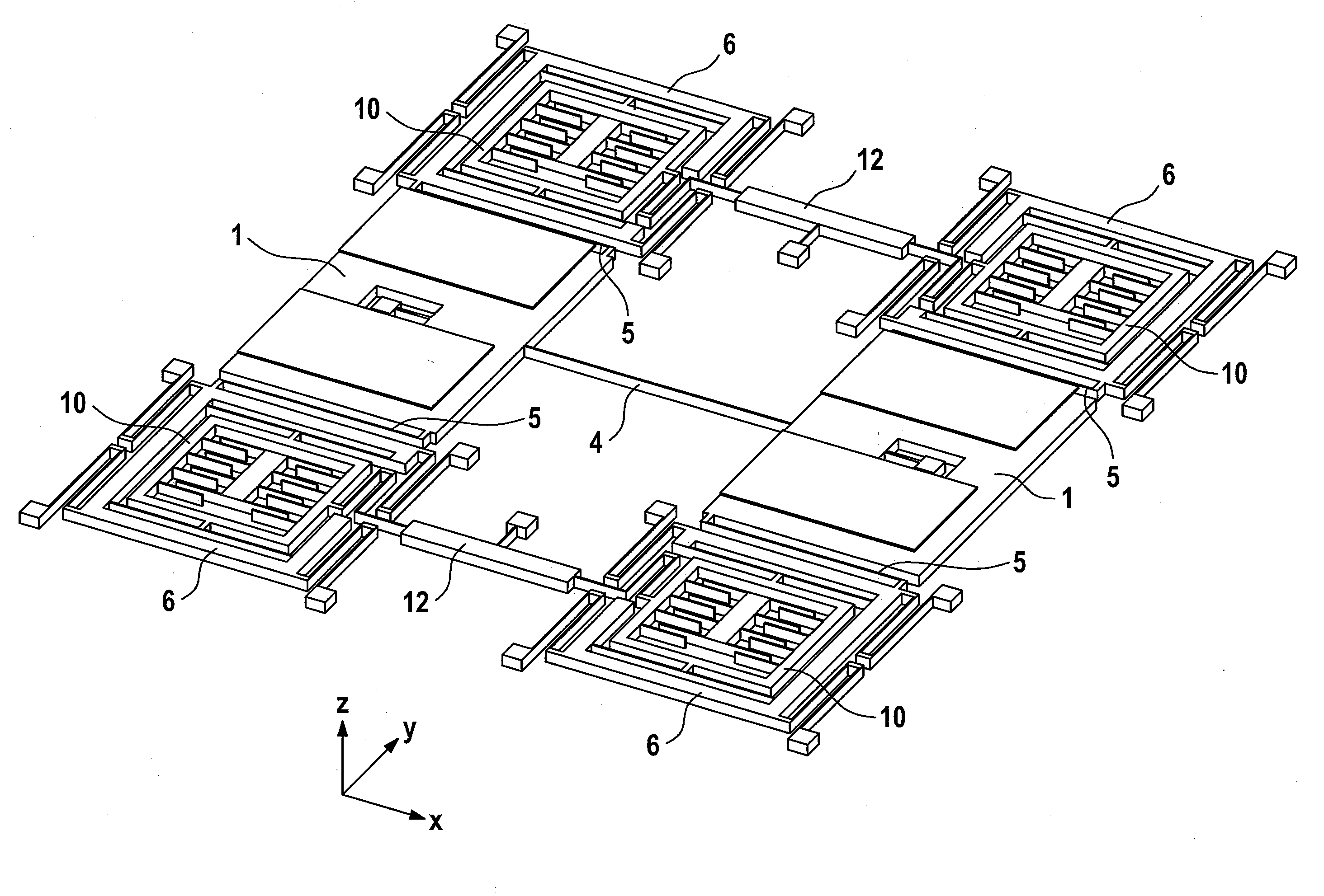
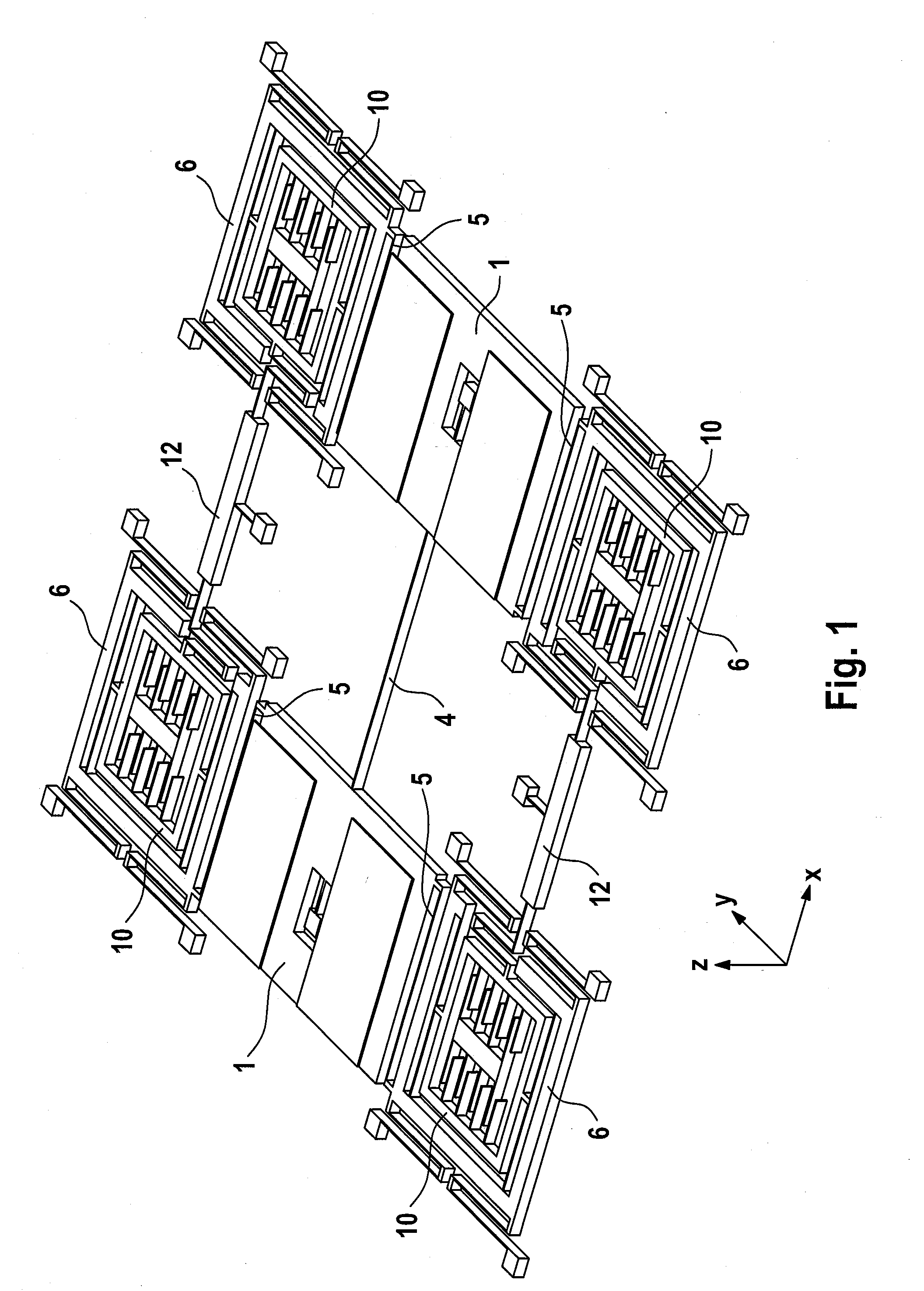
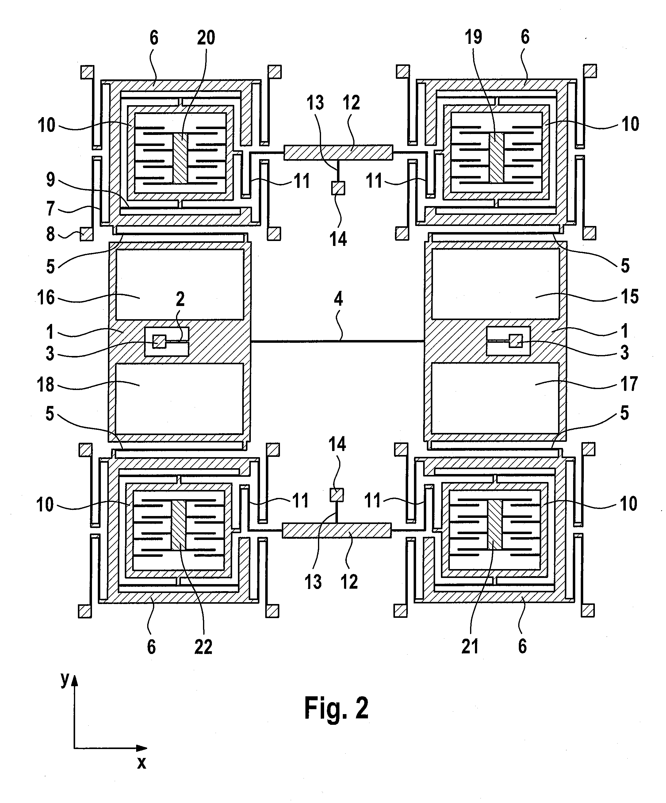
[0044]FIG. 1 and FIG. 2 show an example of a rotation rate sensor which can detect both rotational speeds about the z axis, as the second sensitive axis, and about the y axis, as the first sensitive axis. The sensor consists of two masses 1, as the first and second seismic masses which are connected to anchors 3 and to one another via spring elements 2, 4 such that they can carry out rotational movements about the z axis, with the first and second seismic masses 1 moving in antiphase during the course of the drive mode, drive oscillation or primary mode, see FIG. 3 and FIG. 4. The suspension of the first and second seismic masses 1 furthermore allows rotational movements about the x axis, with the coupling spring 4 also providing coupling between the two masses 1 in this oscillation. There is therefore a mode, as the first read mode, in which seismic masses 1 oscillate in antiphase, or in the opposite direction, about the y axis, see FIG. 6. Apart from mutually antiphase rotations a...


PUM


Abstract

A micromechanical rotation rate sensor has at least one first and one second seismic mass coupled to at least one first drive device and are suspended such that the first and second seismic masses are driven such that they are deflected in antiphase in one drive mode, with the rotation rate sensor being designed such that it can detect rotation rates about at least two mutually essentially orthogonal sensitive axes, wherein at least the first and second seismic masses are designed and suspended such that they oscillate in antiphase in a first read mode when a first rotation rate about the first sensitive axis is detected, and the first and second seismic masses and/or additional seismic masses are designed and suspended such that they oscillate in antiphase in a second read mode when a second rotation rate about the second sensitive axis is detected.

Description

CROSS REFERENCE TO RELATED APPLICATIONS[0001]This application is the U.S. National Phase Application of PCT International Application No. PCT / EP2010 / 063248, filed Sep. 9, 2010, which claims priority to German Patent Application No. DE 10 2009 029 310.8, filed Sep. 9, 2009, and German Patent Application No. DE 10 2009 029 311.6, filed Sep. 9, 2009, the contents of such applications being incorporated by reference herein.FIELD OF THE INVENTION[0002]The invention relates to a micromechanical rotation rate sensor comprising a substrate whose base surface is aligned parallel to the x-y plane of a Cartesian coordinate system (x, y, z), with the rotation rate sensor having at least one first and one second seismic mass which are coupled to at least one first drive device and are suspended such that the first and the second seismic masses are driven such that they are deflected in antiphase in one drive mode, with the rotation rate sensor being designed such that it can detect rotation rate...

Claims


Application Information

Patent Timeline
Patent Type & Authority Applications(United States)
IPC IPC(8): G01C19/56G01C19/574
CPCG01C19/574G01C19/5719G01C19/5642
Inventor GUNTHER, STEFANSCHMID, BERNHARD
Owner CONTINENTAL TEVES AG & CO OHG
Why Eureka
Try Eureka