Tool for a street milling, coal-cutting or mining machine

a technology for street milling and mining machines, which is applied in the direction of cutting machines, drilling accessories, slitting machines, etc., can solve the problems of the region of contact surface on which the wear protection element is supported and which is arranged around the receiver gradually wears away, and the centering extension cannot be kept in pla

Inactive Publication Date: 2003-09-16
BETEK BERGBAU UND HARTMETALLTECHN KARL HEINZ SIMON
View PDF16 Cites 44 Cited by
  • Summary
  • Abstract
  • Description
  • Claims
  • Application Information

AI Technical Summary

Problems solved by technology

During operation, the region of the contact surface on which the wear protection element is supported and which is arranged around the receiver gradually w

Method used


Image

  • Tool for a street milling, coal-cutting or mining machine
  • Tool for a street milling, coal-cutting or mining machine
  • Tool for a street milling, coal-cutting or mining machine

Examples


Embodiment Construction

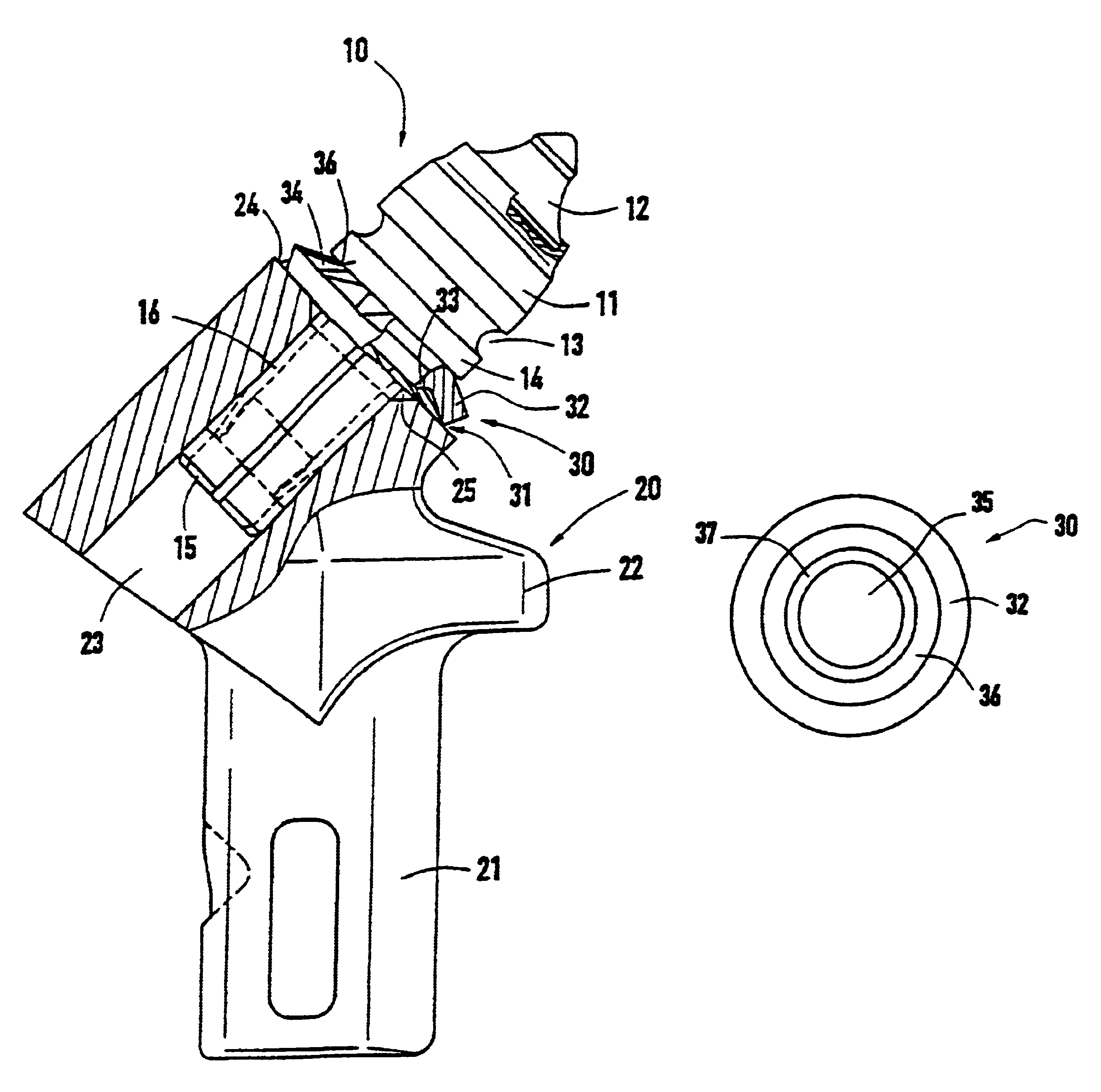
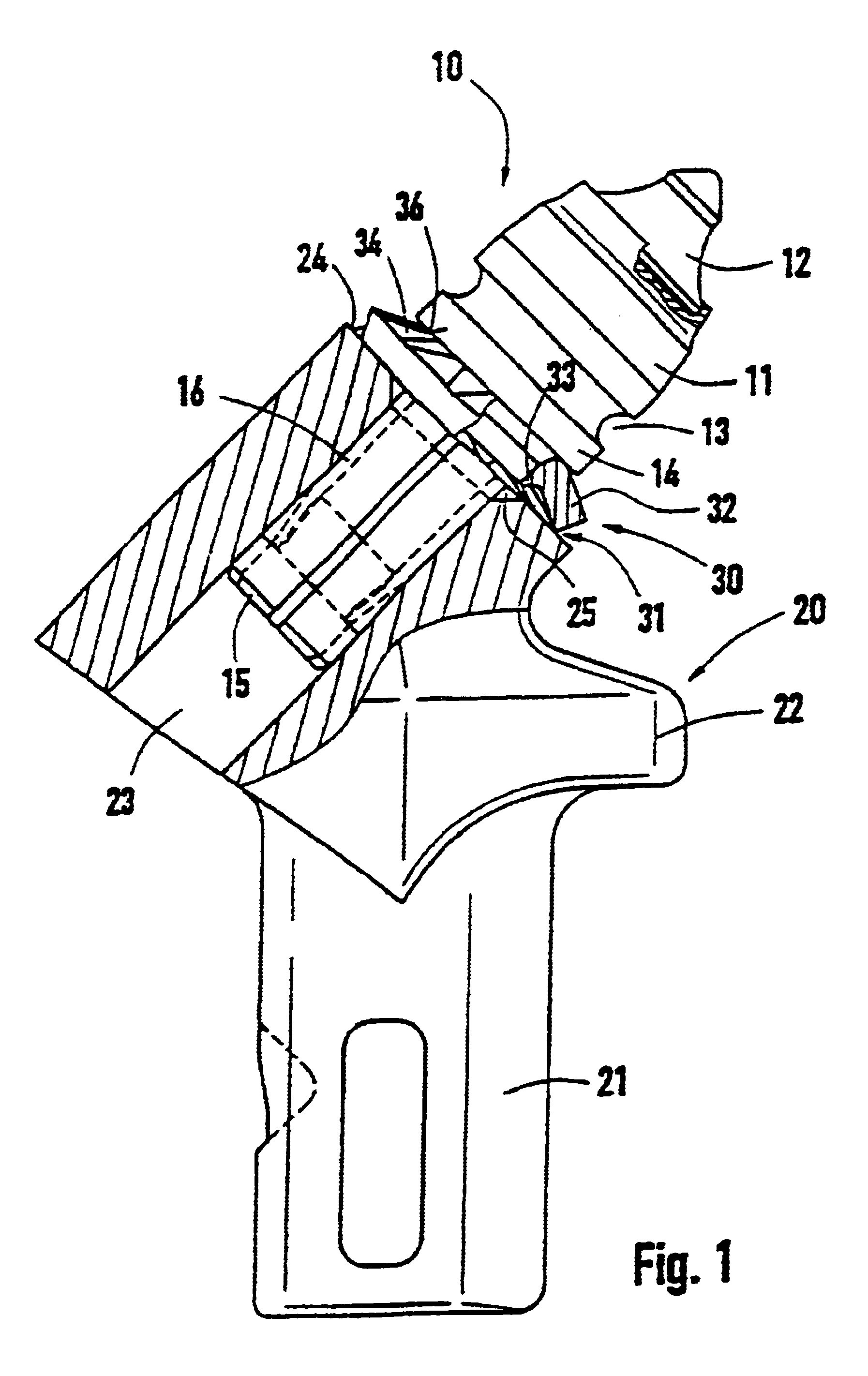
FIG. 1 shows a chisel holder 20 with a base part 22. The base part 22 carries a plug attachment 21 that can fix the chisel holder 20 to a holder part so that it can be removed. The holder part can then be attached to a milling roller or a coal-cutting machine or the like. For the sake of clarity, the holder part and the milling roller are not shown in FIG. 1. The base part 22 has a receiver 23. The receiver 23 is bored into the base part 22 starting from a level contact surface 24. The receiver 23 expands outwards by means of a centering extension 25 at the contact surface 24. A chisel 10 is fixed to the chisel holder 20. The chisel 10 comprises a chisel head 11 and a chisel shaft 15. The chisel head 11 has a receiver on its front side, in which a bit 12 is soldered. In an intermediate region, the chisel head 11 has a circumferential groove 13 that enables the disassembly of the chisel 10 from the chisel holder 20, with a tool. In the transition region to the chisel shaft 15, the ch...


PUM


Abstract

A tool for a street milling, coal-cutting mining machine or the like which includes a chisel with a chisel head and a chisel stem. The chisel stem is rotatably mounted in a receiver of a chisel holder. A perforated wearing protection element is mounted on the chisel head. The chisel head sits closely on the chisel holder while embracing the interposed wearing protection element. This invention achieves improved wearing protection behavior of such a tool. Thus, the inventive wearing protection element has one or more spring elements that elastically support the chisel head by way of the chisel holder.

Description

1. Field of the InventionThis invention relates to a tool for a street milling, coal-cutting, mining machine or the like which has a chisel with a chisel head and a chisel shaft. The chisel shaft is rotatably mounted in a receiver of a chisel holder. A perforated wear protection element is mounted on the chisel head with the chisel head sitting closely on the chisel holder with the wear protection element interposed.2. Description of Related ArtA tool is known from European Patent Reference EP 0 413 917 A1, where the wear protection element is formed as a circular steel sheet disk, from which an opening is punched in the center. The opening is extended in the direction of the chisel head. A chamfered part of the chisel head lies in this extension. The wear protection element lies flat on a contact surface of the chisel holder. During use of the tool, waste material can get past the chisel head and the wear protection element and reach the receiver. In this position, this material ca...

Claims


Application Information

Patent Timeline
IPC IPC(8): B28D1/18E21C35/18E21C35/00E21C35/197
CPCB28D1/188E21C35/18E21C35/197E21C2035/1826E21C35/188
Inventor KAMMERER, KARL
Owner BETEK BERGBAU UND HARTMETALLTECHN KARL HEINZ SIMON
Why Eureka
Try Eureka