
Display panel and color filter therein

a color filter and display panel technology, applied in non-linear optics, instruments, optics, etc., can solve the problems of affecting display quality, the thickness of the black matrix layer b>1/b>b>13/b> or the color filter layer b>1/b>b>12/b> may not be so uniform, etc., to achieve better elastic deformation ability

Inactive Publication Date: 2006-10-26
AU OPTRONICS CORP
View PDF4 Cites 22 Cited by
  • Summary
  • Abstract
  • Description
  • Claims
  • Application Information

AI Technical Summary

Benefits of technology

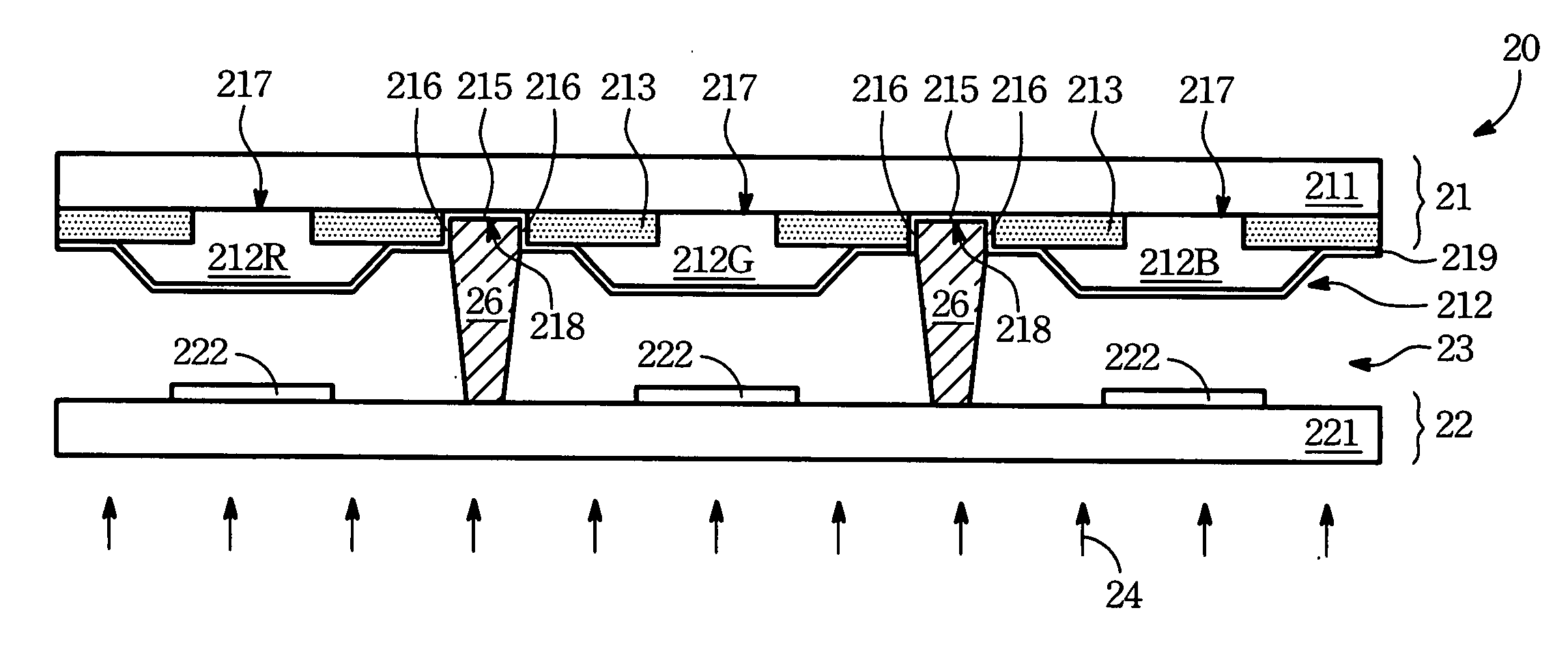
[0012] It is therefore a primary objective of present invention to provide a pillar spacer, which is able of providing a better elastic deformation ability.
[0013] It is another objective of present invention to provide a plurality of pillar spacers, which is able to maintain an uniform distance between the first substrate and the second substrate.
[0014] It is another objective of present invention to provide a plurality of pillar spacers, which is able to be controlled its height more easily in the manufacturing process.
[0015] It is another objective of present invention to provide a pillar spacer, which is able to bear more stresses.

Problems solved by technology

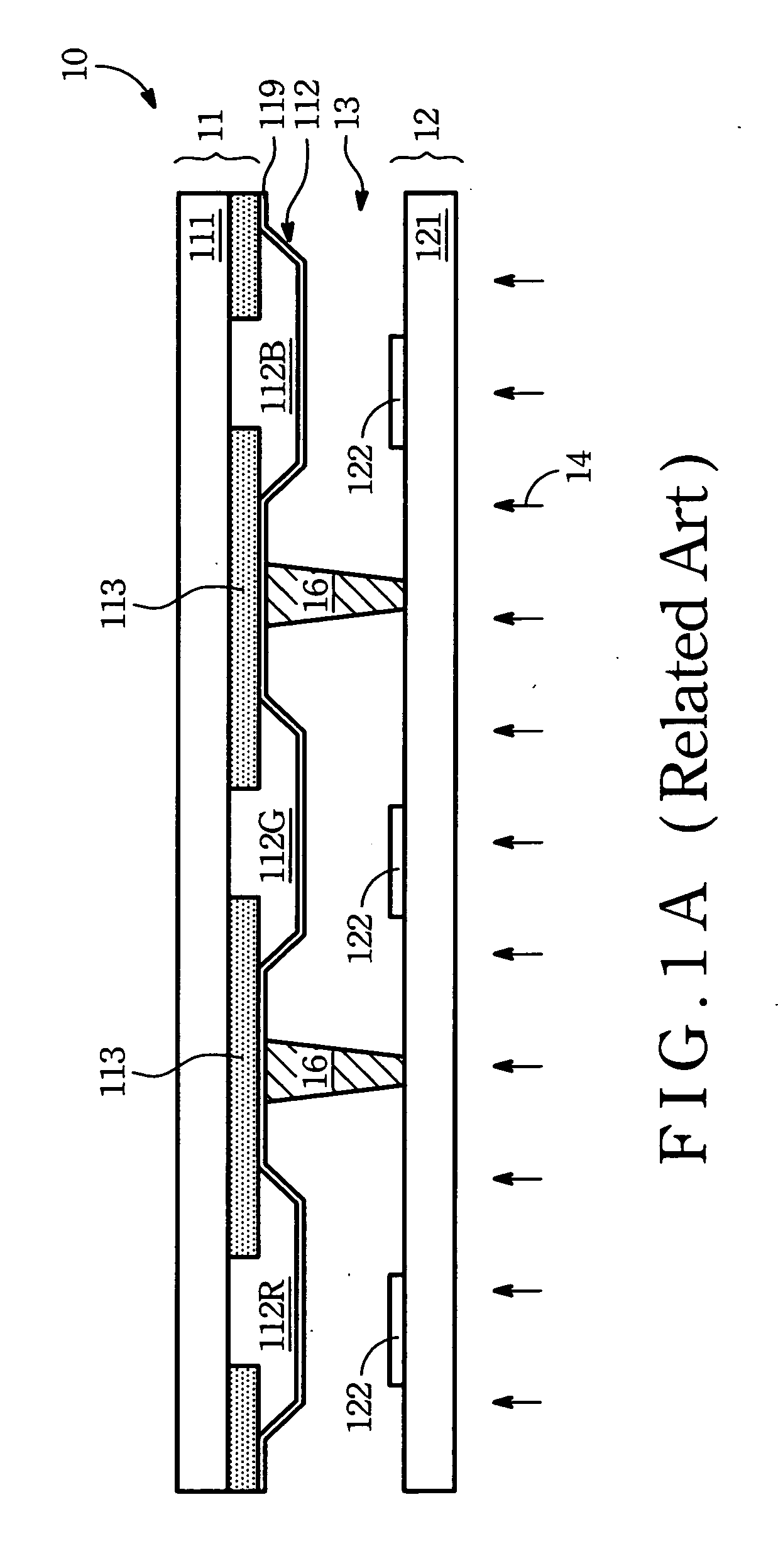
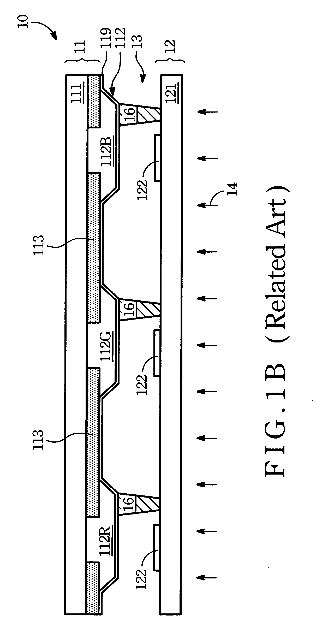
In other words, to dispose the pillar spacers 16 in the effective display areas may defeat display quality.
However, the thickness of the black matrix layer 113 or the color filter layer 112 may not be so uniform because of their fabrication process.
This and other mentioned drawbacks not only influence the product stability, but also have an effect on displaying quality of the effective displaying areas.

Method used


Image

  • Display panel and color filter therein
  • Display panel and color filter therein
  • Display panel and color filter therein

Examples


Embodiment Construction

[0030] Referring to FIG. 2A. FIG. 2A is a sectional view of a display panel 20 according to the first embodiment of the present invention. The display panel 20 comprises a first substrate 21, a second substrate 22 and a plurality of pillar spacer 26. The first substrate 21 comprises a first base 211, a color filter layer 212 and a black matrix layer 213 with a plurality of openings 218. The second substrate 22 is disposed below the first substrate 21 and is separated at a predetermined distance from the first substrate 21. The plurality of pillar spacer 26 is used for maintaining the predetermined distance. Each pillar spacer 26 has a first end 261 and a second end 262, wherein the first end 261 of each pillar spacer 26 is inserted into the portion of the plurality of openings 218, and the second end 262 of each pillar spacer 26 extends to contact with the second substrate 22. In practice, the plurality of pillar spacer 26 may be made of photo resist materials. A liquid crystal laye...


PUM


Abstract

A display panel comprising a first substrate, a second substrate and a plurality of pillar spacers is provided. The first substrate comprises a first base and a black matrix layer with a plurality of openings. The black matrix layer is disposed on the lower surface of the first base. The second substrate is disposed below the first substrate and separated at a predetermined distance from the first substrate. The plurality of pillar spacers for maintaining the predetermined distance. Each of the pillar spacer having a first end and a second end. The first end is inserted into the portion of the plurality of openings, and the second end extends to contact with the second substrate.

Description

BACKGROUND OF THE INVENTION [0001] (1) Field of the Invention [0002] The present invention relates to a display panel, and more particularly, to a display panel that is composed of a pair of substrates. [0003] (2) Description of the Prior Art [0004] Referring to FIG. 1A. FIG. 1A is a sectional view of a conventional liquid crystal panel 10. The liquid crystal panel 10 comprises a first substrate 11, a second substrate 12, and a liquid crystal layer 13 is disposed between the first substrate 11 and the second substrate 12. The liquid crystal layer 13 comprises a plurality of liquid crystal molecules. [0005] The first substrate 11, generally as a color filter substrate, comprises a first base 111, a color filter layer 112, a black matrix layer 113 and a common electrode layer 119. The color filter layer 112, disposed on the lower surface of the first base 111, comprises an array of red filter units 112R, an array of green filter units 112G and an array of blue filter units 112B, which...

Claims


Application Information

Patent Timeline
IPC IPC(8): G02F1/1339
CPCG02F1/133512G02F1/13394
Inventor CHEN, WAN-JUNGHUANG, HSUEH-YINGCHENG, KUO-HSING
Owner AU OPTRONICS CORP
Learn More