Multiple paint roller holder

a multi-purpose, paint-type technology, applied in the direction of decorative arts, portable power-driven tools, decorative surfaces, etc., can solve the problems of constant repainting, limiting the painting stroke to the vertical, up and down directions, and time-consuming and inefficient activity, so as to facilitate mounting and removal, the effect of facilitating faster painting of surfaces

Inactive Publication Date: 2013-06-11
KING FAHD UNIVERSITY OF PETROLEUM AND MINERALS
View PDF16 Cites 4 Cited by
  • Summary
  • Abstract
  • Description
  • Claims
  • Application Information

AI Technical Summary

Benefits of technology

[0006]The multiple paint roller holder includes a roller frame and a handle connected to the roller frame. The handle is preferably connected to the frame by a bent or angled neck to place the handle in a raised position. The roller frame includes an upper cross member having corresponding upper roller holding pins, a lower cross member having corresponding lower roller holding pins, and an extendable center beam interconnecting the upper and lower cross members. Each pair of upper roller holding pins and lower roller holding pins rotatably holds a paint roller therebetween. The extendable center beam allows temporary lengthening of the center beam to facilitate mounting and removal of a plurality of paint rollers disposed vertically within the frame. The multiple paint rollers held thereby facilitate faster painting of surfaces.

Problems solved by technology

While the conventional paint roller can paint surfaces satisfactorily, it is a time-consuming and inefficient activity.
This also leads to constant repainting over sections already worked in an effort to obtain an even coat due to uneven application of paint from a near-depleted roller.
Moreover, the construction of the typical paint roller devices limits the painting strokes to the vertical, up and down directions on the surface being painted.

Method used


Image

  • Multiple paint roller holder
  • Multiple paint roller holder
  • Multiple paint roller holder

Examples


Embodiment Construction

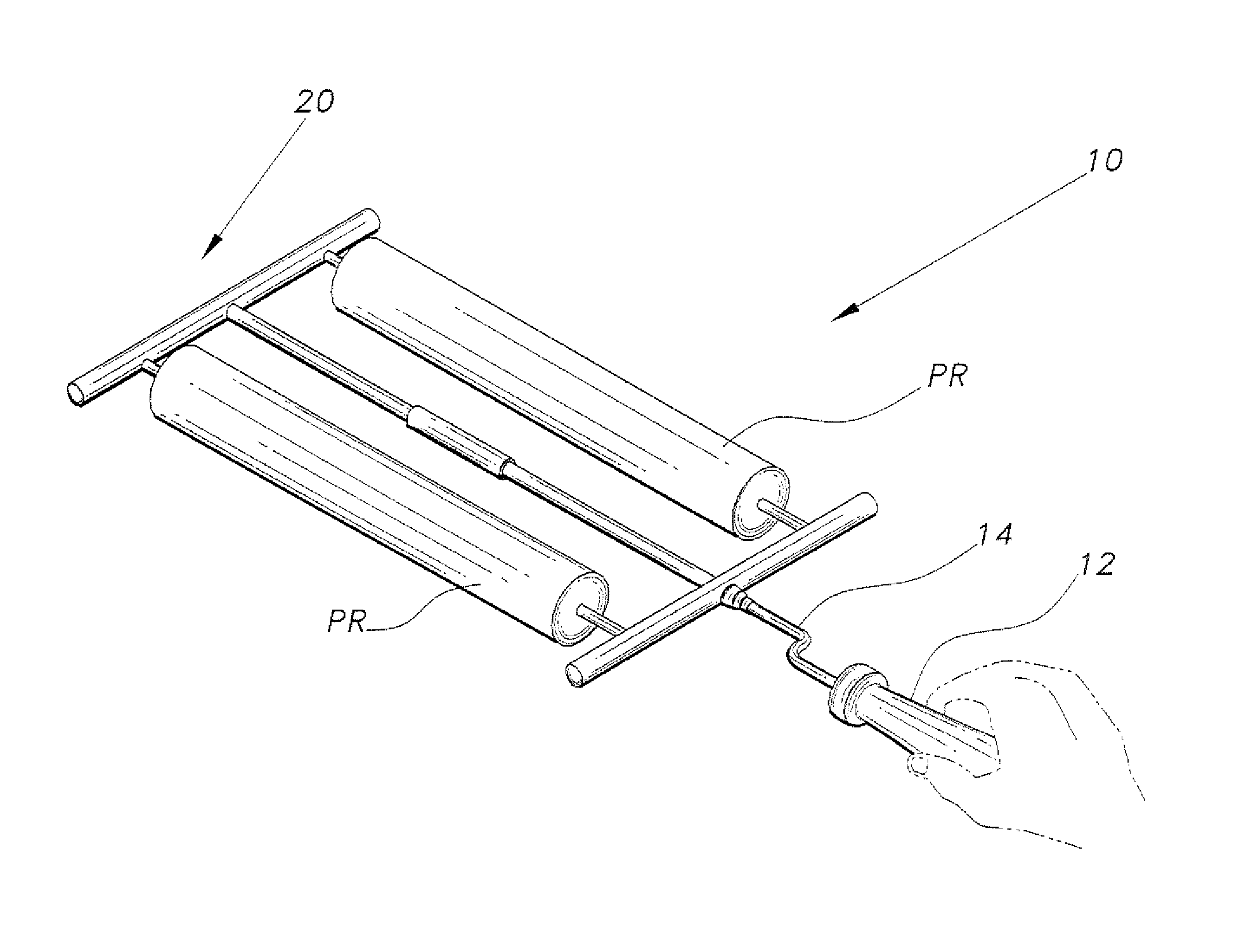
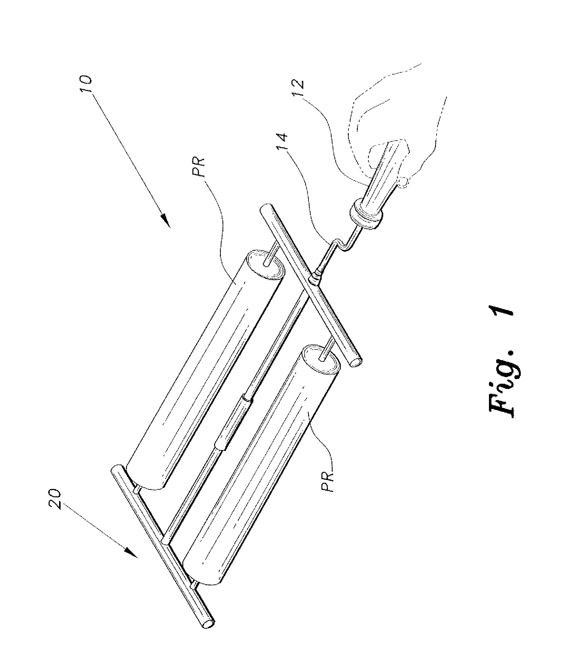
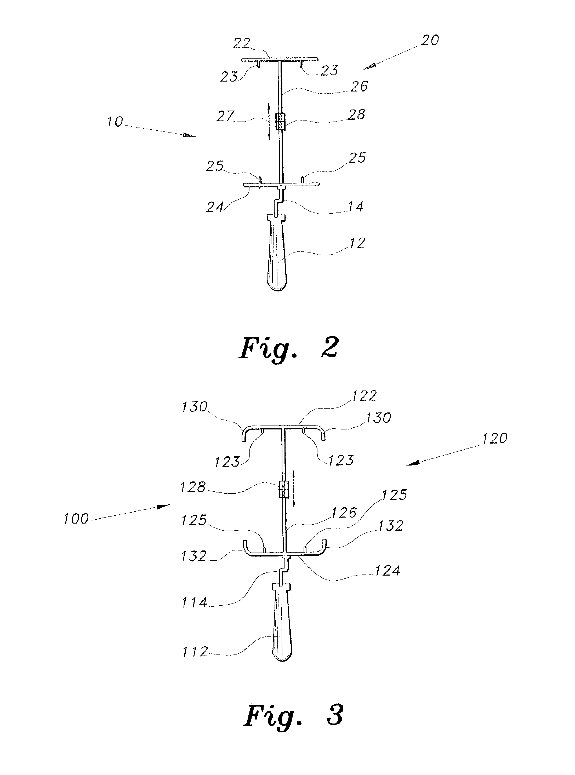
[0012]The multiple paint roller holder, a first embodiment of which is generally referred to in the drawings by the reference number 10, provides faster execution of the task with improved versatility for painting in various directions. As shown in FIGS. 1 and 2, the multiple paint roller holder 10 includes a roller frame 20 for holding a plurality of paint rollers PR and a handle 12 attached thereto. The handle 12 includes an elongate neck 14 mounted directly to the roller frame 20. The connection can be fixed, freely rotating or selectively oriented at an angle. The neck 14 is preferably configured as a bent neck forming a zigzag pattern as shown, or as a straight neck disposed at an angle with respect to the connection to the roller frame 20. The bent neck 14 permits the user to hold the handle 12 at a raised, comfortable position from the surface being painted for moving the roller frame 20 in any desired direction, e.g., horizontal, vertical, arcuate and points between. In this...


PUM


Abstract

The multiple paint roller holder includes a roller frame and a handle connected to the roller frame. The handle is preferably connected to the frame by a bent or angled neck to place the handle in a raised position. The roller frame includes an upper cross member having corresponding upper roller holding pins, a lower cross member having corresponding lower roller holding pins, and an extendable center beam interconnecting the upper and lower cross members. Each pair of upper roller holding pin and lower roller holding pin rotatably holds a paint roller therebetween. The extendable center beam allows temporary lengthening of the center beam to facilitate mounting and removal of a plurality of paint rollers disposed vertically within the frame. The multiple paint rollers held thereby facilitate faster painting of surfaces.

Description

BACKGROUND OF THE INVENTION[0001]1. Field of the Invention[0002]The present invention relates to painting devices, and particularly to a multiple paint roller holder that provides fast performance and increased versatility.[0003]2. Description of the Related Art[0004]Painting one's living and working environment to suit one's aesthetics and décor has been a common practice for a long time. Many painting devices are available to facilitate this task, and these devices range from simple paint brushes to powered spray painters. The paint roller is one of the most common painting devices in current use. These typically include a single paint roller rotatably mounted to a holder. A handle is usually attached to the holder for the user to push and pull during the process of painting a surface. While the conventional paint roller can paint surfaces satisfactorily, it is a time-consuming and inefficient activity. The user must repeatedly dip the roller in a pan of paint because the amount o...

Claims


Application Information

Patent Timeline
Patent Type & Authority Patents(United States)
IPC IPC(8): B05C17/02
CPCB05C17/023B05C17/0217
Inventor DONDURUR, MEHMETSAHIN, AHMET Z.
Owner KING FAHD UNIVERSITY OF PETROLEUM AND MINERALS
Why Eureka
Try Eureka