Brush assembly for self-propelled pool and tank cleaner

a self-propelled, pool-based technology, applied in the direction of gymnasium, construction, buildings, etc., can solve the problems of affecting the cleaning effect of the pool, so as to facilitate mounting and removal

Inactive Publication Date: 2016-02-18
AQUA PRODS
View PDF8 Cites 6 Cited by
  • Summary
  • Abstract
  • Description
  • Claims
  • Application Information

AI Technical Summary

Benefits of technology

[0026]In an aspect, the endcaps include a circular flange having cutout sized to conform to the pair of adjacently positioned ridges. Each endcap can be positioned about a corresponding end of the roller such that the pair of adjacent ridges extends through a corresponding cutout in the circular flange of the endcap. In another aspect, the circular flange of the endcap is positioned between the inward shoulder portion and the inner surface of the web material. In still another aspect, each endcap includes a mounting hub extending coaxially in a direction along the longitudinal axis of the roller for enabling installation of the brush assembly into the self-propelled robotic cleaning apparatus. In still another aspect, at least one of the endcap mounting hubs is resiliently mounted to facilitate mounting and removal of the brush assembly from the cleaning apparatus.

Problems solved by technology

Cleaning brushes can be made of a foamed polymer or plastic sponge material, in which case they are subject to wear and tear due to their continuous rotating contact with the bottom and side wall surfaces of the pool.
Although the pin secures the first and second elements together, aligning and interleaving the first and second elements while inserting the pin can be time consuming.
While each type of cleaning brush possesses certain advantages, and is intended for use under specific conditions, these prior art brushes face a drawback in the effort associated with removing a worn brush and installing a replacement cleaning brush.
However, considerable effort is required to pull and properly fit the replacement brush on the shaft.
Therefore, after the tabs and slots of the overlying ends are brought into mating alignment, it can be difficult, especially for residential pool owners, to install the new brushes.
Moreover, unless the interlocking elements of these brushes are fully positioned in their precise interlocking configuration, the possibility of disengagement is appreciable, in which case the brush can become loose or detached from the rotating shaft, so that it does not rotate properly and no cleaning of the pool surface is affected.
It is also known, in the case of the molded brushes having a flat backing surface, that mildew and dirt can be formed during periods of non-use and storage between the mounting shaft and the back, causing the elements to stick together and necessitating removal of the dirt, mold and mildew before a new brush can be installed.

Method used


Image

  • Brush assembly for self-propelled pool and tank cleaner
  • Brush assembly for self-propelled pool and tank cleaner
  • Brush assembly for self-propelled pool and tank cleaner

Examples


Embodiment Construction

[0052]For purposes of providing a better understanding the invention, terms connoting direction and positioning of components are defined as follows:

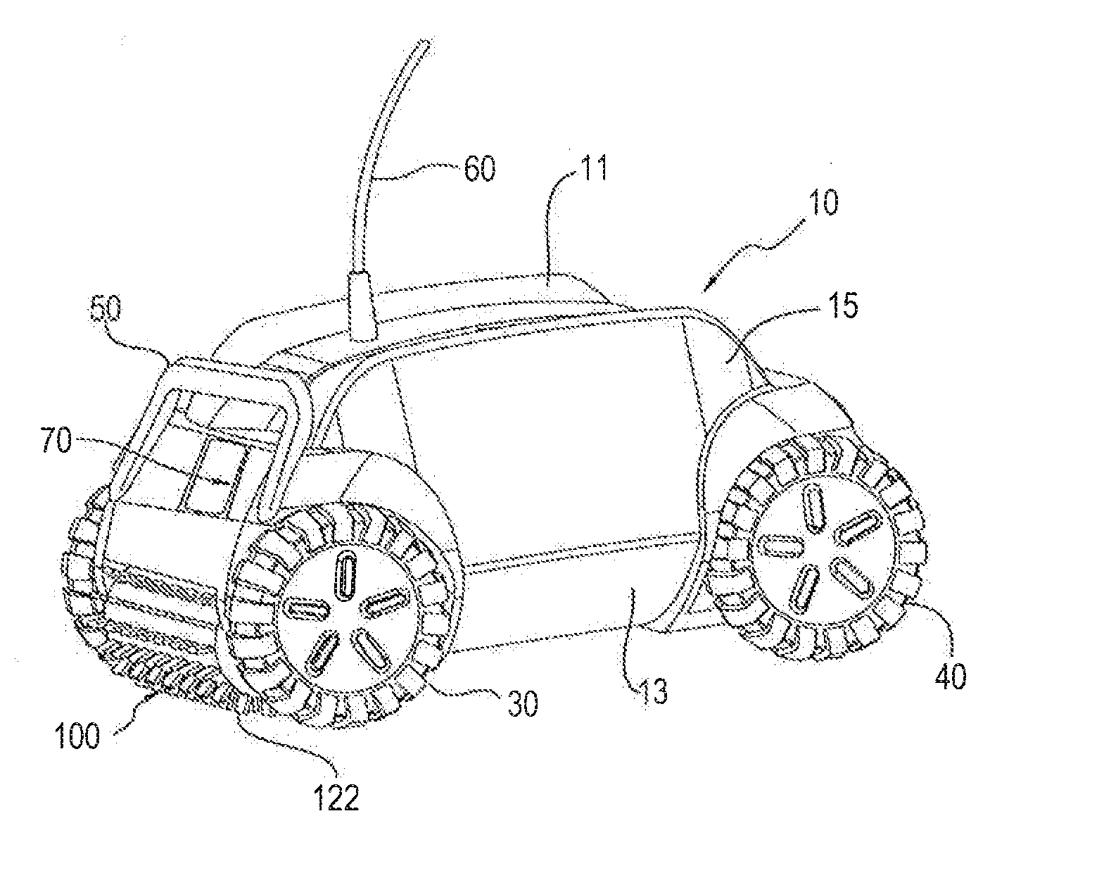
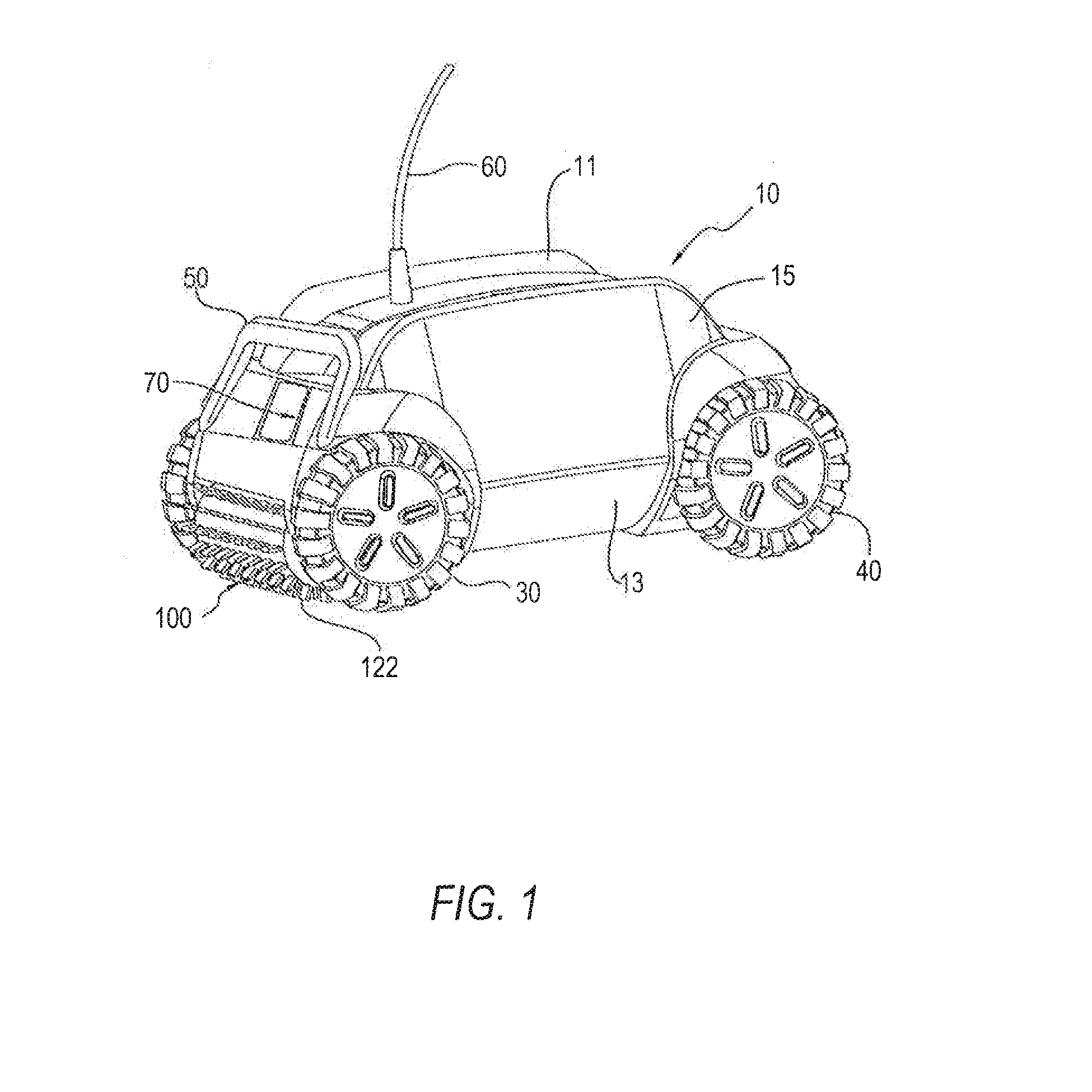
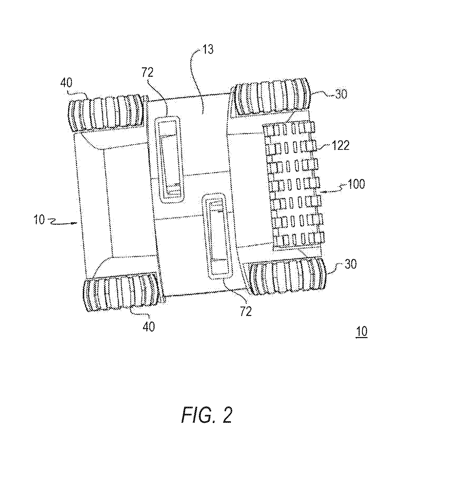
[0053]The terms “cleaning apparatus”, “cleaning vehicle” and “pool cleaner” as used herein are interchangeable and defined as a self-propelled vehicle that is submersible in water and operable to move and filter debris located along a surface of the pool.

[0054]longitudinal axis of the cleaner is defined as a single, fixed axis extending centrally through the cleaner parallel to a pool surface beneath the cleaner and in the general direction of movement;

[0055]movement of the cleaner in a forward direction is the direction that the cleaner is generally being propelled or driven along its cleaning path;

[0056]movement of the cleaner in a reverse direction is a direction that is generally opposite to the previous forward direction along the cleaning path;

[0057]the front of the cleaner is defined as the portion of the cleaner generally extend...


PUM


Abstract

A rotatable brush assembly for a cleaning apparatus includes a cylindrical roller formed by first and second arcuate members. Each arcuate member has an inner longitudinal portion and an opposing longitudinal free end, the inner longitudinal portions being adjacently hinged together. The longitudinal free ends are positioned adjacently when the hinge is in a closed position. A web includes spaced-apart cleaning members extending outward from its external surface. Opposing longitudinal ends substantially conform to the opposing longitudinal free ends of the roller and its width is dimensioned such that an inner surface of the web wraps around and directly covers an outer surface of the cylindrical roller. Each longitudinal end of the web terminates in a U-shaped flange which defines a channel that conforms to and interfaces with one of the longitudinal free ends of the roller. Opposing end caps are disposed over opposing ends of the elongated cylindrical roller.

Description

CROSS-REFERENCE TO RELATED APPLICATION[0001]This patent application is a continuation-in-part of U.S. application Ser. No. 13 / 681,899, filed Nov. 20, 2013, and this application also claims the benefit of U.S. provisional Application No. 62 / 073,346, filed Oct. 31, 2014, the contents of which are incorporated by reference herein in their entireties.FIELD OF THE INVENTION[0002]The present invention relates to a submersible robotic pool and tank cleaning apparatus, and more specifically to a motor driven rotatable brush assembly for stirring up and cleaning undesirable contaminants and debris from a surface of a pool or tank environment.BACKGROUND OF THE INVENTION[0003]Robotic pool cleaning devices are mounted on rotatable supports, such as wheels, brushes and / or tracks, and are propelled or otherwise travel along submerged surfaces of a pool, tank or the like and, through the use of suction, thereby “vacuum” the pool surfaces over which they pass. The pool cleaning devices can be prope...

Claims


Application Information

Patent Timeline
Patent Type & Authority Applications(United States)
IPC IPC(8): E04H4/16A46B13/00A46B13/02
CPCE04H4/1654A46B13/001A46B13/02
Inventor KLEBANOV, ALEKSANDRLONDONO, WILLIAM
Owner AQUA PRODS
Why Eureka
Try Eureka