Fluid divider valves

a technology of divider valves and valves, applied in the field of valves, can solve the problems of reducing the operational life of components in typical dual-fuel engines, and reducing the operational life of components

Active Publication Date: 2013-06-25
COLLINS ENGINE NOZZLES INC
View PDF4 Cites 39 Cited by
  • Summary
  • Abstract
  • Description
  • Claims
  • Application Information

AI Technical Summary

Benefits of technology

[0008]The subject invention is directed to a new and useful a fluid divider valve. The fluid divider valve includes a housing defining an internal longitudinal bore having a flui

Problems solved by technology

Corrosive compounds degrade engine components and reduce their operational life.
In short, cross talk in the l

Method used


Image

  • Fluid divider valves
  • Fluid divider valves
  • Fluid divider valves

Examples


Embodiment Construction

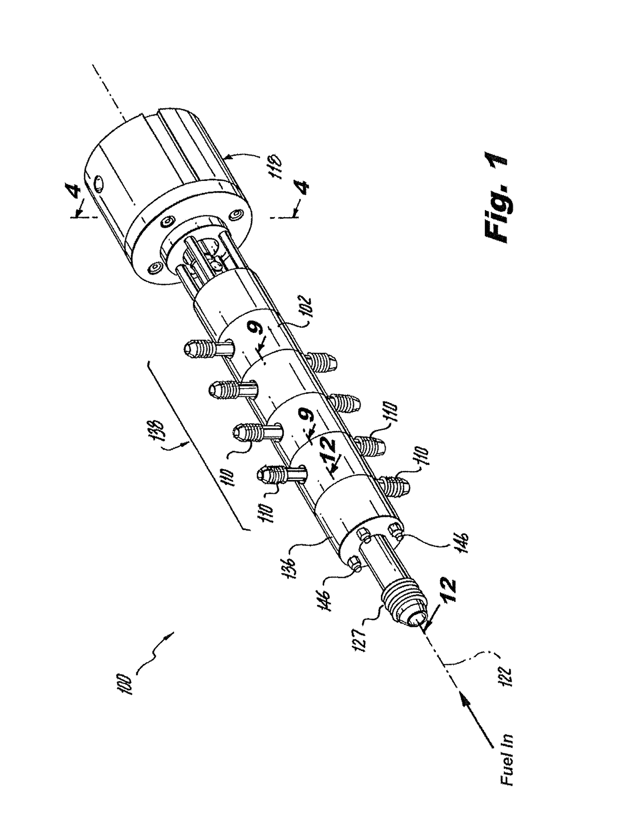
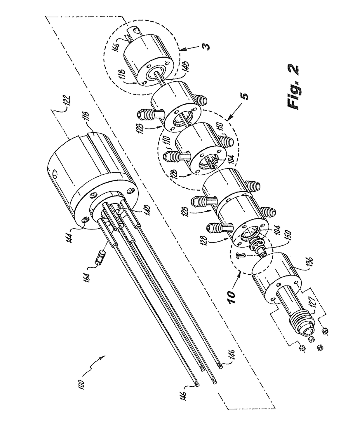
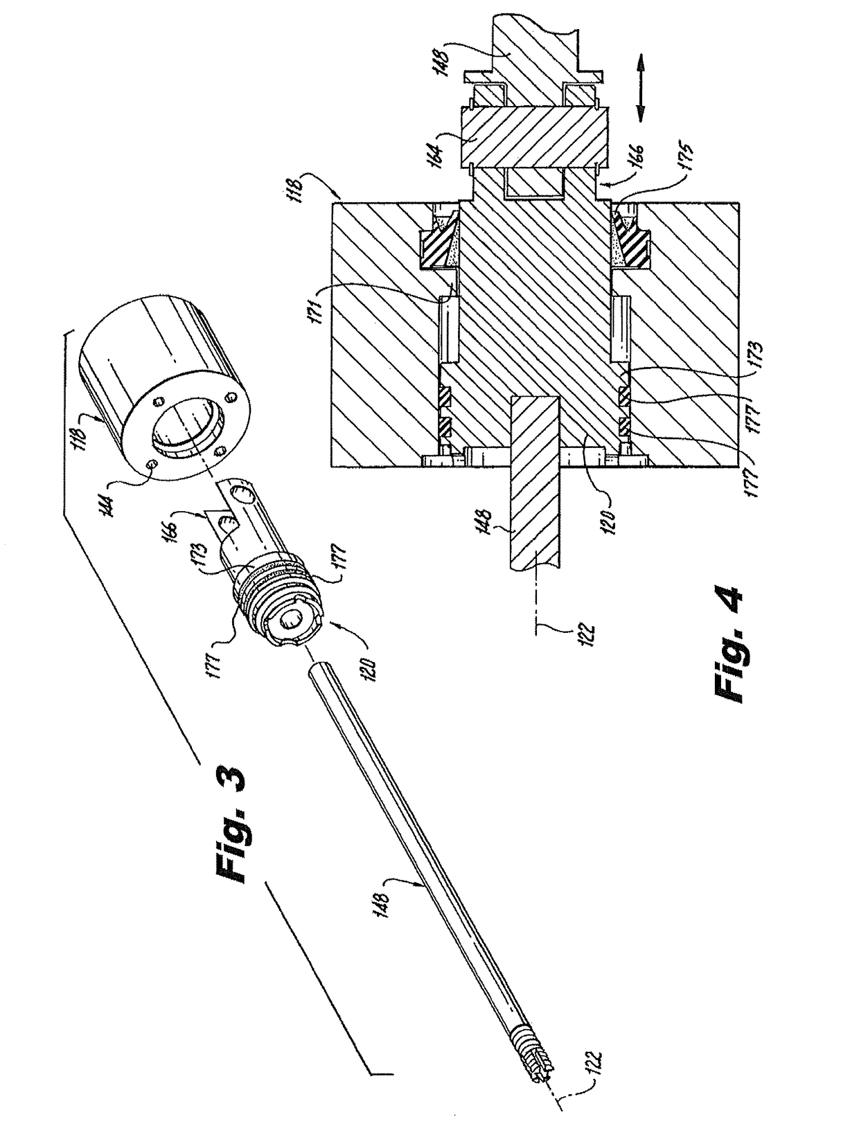
[0048]Reference will now be made to the drawings wherein like reference numerals identify similar structural features or aspects of the subject invention. For purposes of explanation and illustration, and not limitation, a partial view of an exemplary embodiment of a fluid divider valve constructed in accordance with the present invention is shown in FIG. 1 and is designated generally by reference character 100. Other embodiments of fluid divider valves in accordance with the invention, or aspects thereof, are provided in FIGS. 2-23, as will be described.

[0049]The systems and methods of the invention can be used to distribute liquid fuel in dual-fuel gas turbine engines when operating on liquid fuel, and to prevent cross talk when operating on gaseous fuel. The systems and methods of the invention can also be used in any other suitable application where it is desirable to simultaneously open and close multiple fluid ports in fluid communication with a common fluid source.

[0050]Refer...


PUM


Abstract

A fluid divider valve includes a housing defining a longitudinal bore having a fluid inlet. The housing defines a plurality of outlets in fluid communication with the longitudinal bore. A valve shaft is sealingly engaged within the longitudinal bore of the housing. The valve shaft has an internal longitudinal flow passage in fluid communication with the fluid inlet of the housing. The valve shaft has a plurality of radial fluid ports formed therein which extend from the internal longitudinal flow passage to an exterior portion of the valve shaft. The valve shaft is mounted for movement relative to the housing between a first position in which the valve shaft permits fluid communication between the fluid inlet and each of the outlets simultaneously through the radial fluid ports of the valve shaft, and a second position in which the valve shaft prevents fluid communication between the fluid inlet and the outlets.

Description

BACKGROUND OF THE INVENTION[0001]1. Field of the Invention[0002]The present invention relates to valves, and more particularly to fluid divider valves for selectively controlling fluid flow to multiple outlets simultaneously.[0003]2. Description of Related Art[0004]Some gas turbine engines are configured to utilize different fuels from multiple fuel systems. For example, gas turbine engines used for power generation have been configured to selectively operate on either gaseous fuel, such as natural gas, or liquid fuel, such as Diesel or any other suitable liquid petroleum product. The operator of such an engine can choose to operate on gaseous fuel or liquid fuel based on whichever fuel is the most available or cost effective at any given time.[0005]Other dual-fuel gas turbine engines use a first fuel for start up and a second fuel after start up. For example, certain dual-fuel gas turbine engines for an aircraft use a first fuel during start up that is of a type known to ignite rea...

Claims


Application Information

Patent Timeline
IPC IPC(8): F16K11/06
CPCF16K11/0716F02C7/232F23R3/36F23K5/147F23K2301/206F23K2300/206Y10T137/87161Y10T137/87708Y10T137/87804Y10T137/87877Y10T137/87885
Inventor FORST, MICHAEL JOHN
Owner COLLINS ENGINE NOZZLES INC
Why Eureka
Try Eureka