
Distributed antenna system and its data transmission method and central controller

a distributed antenna and data transmission technology, applied in the field of communication, can solve problems such as lack of an established specific solution to the design of distributed antennas

Active Publication Date: 2013-06-25
DATANG MOBILE COMM EQUIP CO LTD
View PDF10 Cites 25 Cited by
  • Summary
  • Abstract
  • Description
  • Claims
  • Application Information

AI Technical Summary

Benefits of technology

[0006]An embodiment of the invention provides a data transmission method for a distributed antenna system to enforce a solution of distributed antennas in a communication system and improve the performance of the communication system. The system includes a central controller and a plurality of radio transceiver units, the data transmission method includes:
[0012]An embodiment of the invention further provides a central controller for a distributed antenna system to enforce a solution of distributed antennas in a communication system and improve the performance of the communication system, the central controller includes:
[0017]An embodiment of the invention further provides a distributed antenna system to enforce a solution of distributed antennas in a communication system and improve the performance of the communication system, the system includes:
[0020]In embodiments of the invention, radio transceiver units measure power information of a received user equipment pilot reference signal, and transmit the power information to a central controller, the central controller selects a set of radio transceiver units for transmission of data to a user equipment according to the power information of the user equipment pilot reference signal transmitted from the radio transceiver units, processes the data according to the set of radio transceiver units and distributes the processed data to the radio transceiver units in the set of radio transceiver units, and the radio transceiver units in the set of radio transceiver units perform downlink transmission of the data, thereby enforcing a solution of distributed antennas in a communication system and improve the performance of the communication system.

Problems solved by technology

In an existing communication system, however, there has been a lack of an established specific solution to a design of distributed antennas.

Method used


Image

  • Distributed antenna system and its data transmission method and central controller
  • Distributed antenna system and its data transmission method and central controller
  • Distributed antenna system and its data transmission method and central controller

Examples


Embodiment Construction

[0028]Embodiments of the invention are detailed hereinafter with reference to the drawings.

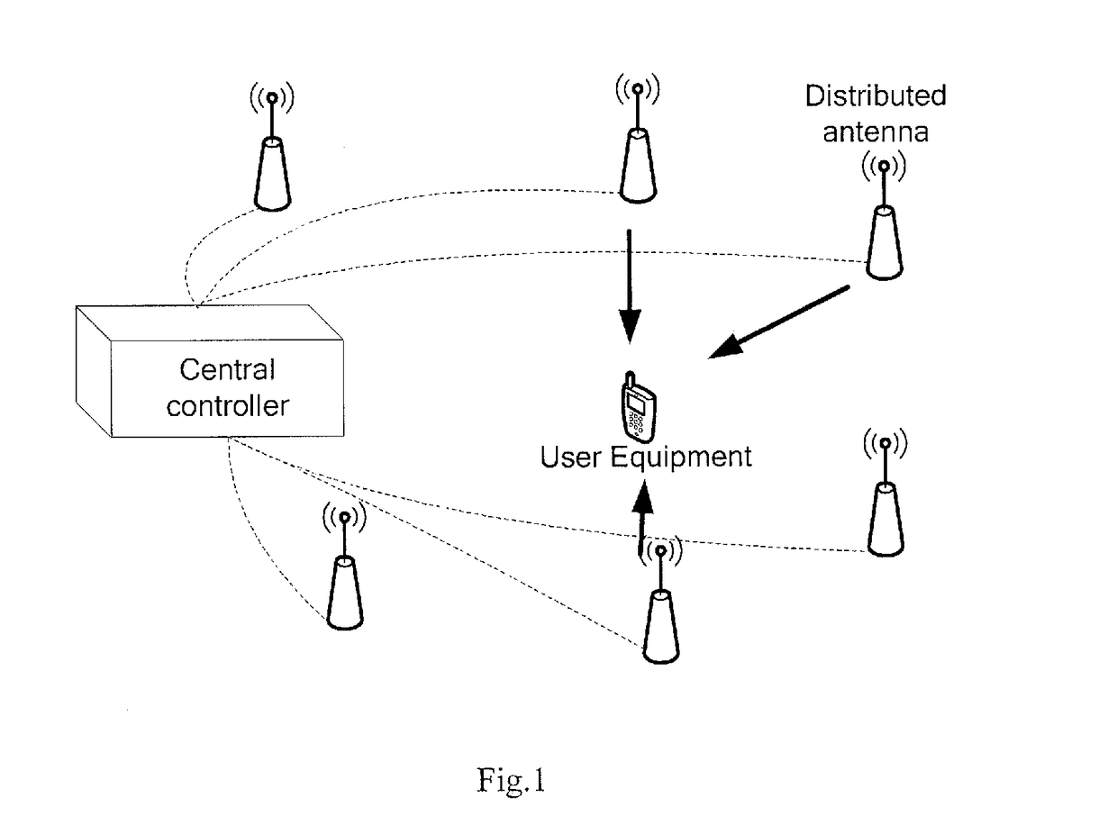
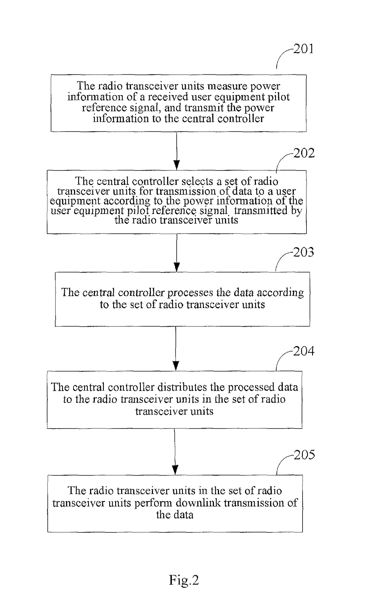
[0029]A distributed antenna system according to an embodiment of the invention includes a central controller and a plurality of radio transceiver units. FIG. 2 illustrates a flow chart of a data transmission process for the distributed antenna system, particularly, the data transmission process comprising the following operations 201-205.

[0030]Operation 201. The radio transceiver units measure power information of a received user equipment pilot reference signal, and transmit the power information to the central controller.

[0031]Operation 202. The central controller selects a set of radio transceiver units for transmission of data to a user equipment according to the power information of the user equipment pilot reference signal transmitted from the radio transceiver units.

[0032]Operation 203. The central controller processes the data according to the set of radio transceiver units.

[0033]Opera...


PUM


Abstract

A data transmission method and central controller for a distributed antenna system and a distributed antenna system. The system includes a central controller and multiple wireless transceiver units. The method includes that wireless transceiver units measure the power of the pilot reference signals received from user terminals and forward this power rate to a central controller; the central controller selects a set of wireless transceiver units for transmitting data to the terminal according to the pilot reference signal power rates of the terminals forwarded by the multiple wireless transceiver units; the central controller performs data processing according to said set of wireless transceiver units; the central controller distributes the processed data to the wireless transceiver units in said set of wireless transceiver units, and the wireless transceiver units in said set perform the downlink data transmission.

Description

CROSS REFERENCE TO RELATED APPLICATIONS[0001]The present application is a US National Stage of International Application No. PCT / CN2009 / 000668, filed 18 Jun. 2009, designating the United States, and claiming priority to Chinese Patent Application No. 200810115310.2 filed 20 Jun. 2008.FIELD OF THE INVENTION[0002]The present invention relates to the field of communications and particularly to a distributed antenna system and a data transmission method thereof and a central controller.BACKGROUND OF THE INVENTION[0003]The International Telecommunication Union (ITU) is very demanding for the performance of the next generation mobile communication system of International Mobile Telecommunications-Advanced (IMT-Advanced), for example, regarding the maximum system transmission bandwidth up to 100 MHz and peak rates of uplink and downlink data transmission up to 500 Mbps / Hz and 1 Gbps / Hz, and also very demanding for an average spectrum efficiency and an edge spectrum efficiency of the system...

Claims


Application Information

Patent Timeline
Patent Type & Authority Patents(United States)
IPC IPC(8): H04W4/00
CPCH04B7/024H04L25/0224H04L5/0051
Inventor SUN, SHAOHUIHOU, YUNZHEWANG, YINGMINXIE, YONGBIN
Owner DATANG MOBILE COMM EQUIP CO LTD
Learn More