
Marking apparatus and marking methods using marking dispenser with machine-readable ID mechanism

a marking dispenser and machine-readable technology, applied in the field of marking devices, can solve the problems of large aggregate cost of marking paint for marking multiple locations, difficult tracking and/or control of marking paint consumption, and waste of significant amount of useful marking pain

Active Publication Date: 2013-06-25
CERTUSVIEW TECH LLC
View PDF487 Cites 35 Cited by
  • Summary
  • Abstract
  • Description
  • Claims
  • Application Information

AI Technical Summary

Benefits of technology

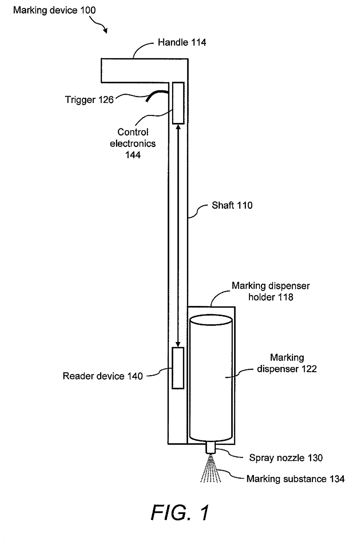
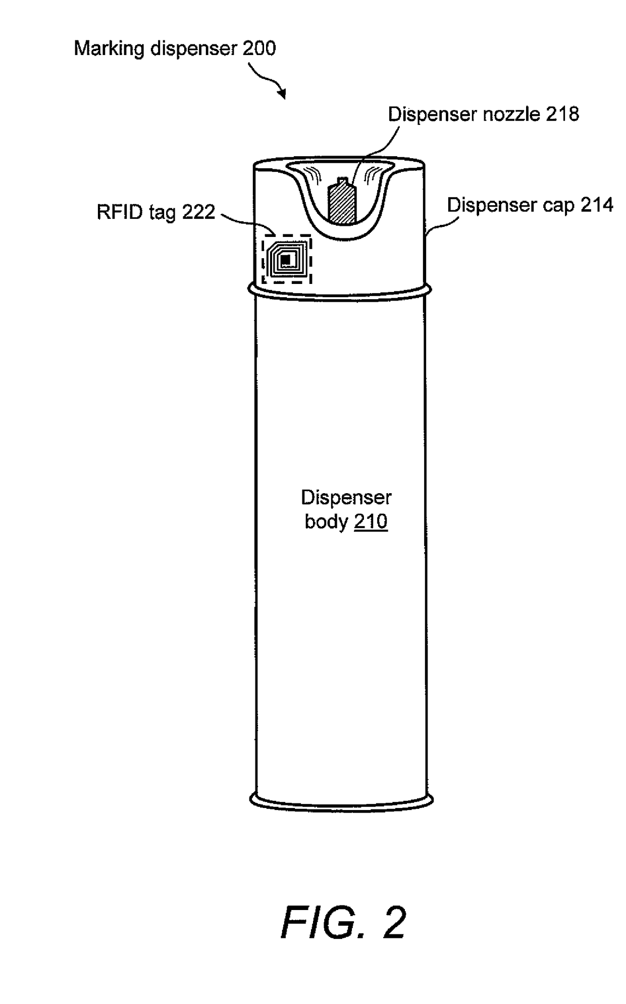
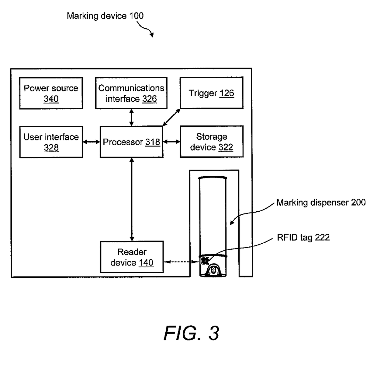
The invention is about a marking apparatus that can be used to indicate the presence or absence of underground facilities in a dig area. The apparatus includes a housing, a marking dispenser holder, and an actuator to dispense marker onto the ground. There is also a reader device to read ID information from an ID mechanism on the marking dispenser, and a processing device to generate marker information based on the ID information. The technical effect of this invention is to provide a convenient and efficient way to indicate the presence or absence of underground facilities in a dig area, which can help to improve safety during construction activities.

Problems solved by technology

Additionally, in the marking industry, the aggregate cost of the marking paint for marking multiple locations may be substantial.
Accordingly, the consumption of marking paint is hard to track and / or control as the cost of individual dispensers is generally thought of as insignificant by the marking technicians who, therefore, tend to be wasteful.
Consequently, over time a significant amount of useful marking paint may be wasted, and, in addition to environmental concerns, the cost of supplying and / or replenishing the marking paint is not optimized.

Method used


Image

  • Marking apparatus and marking methods using marking dispenser with machine-readable ID mechanism
  • Marking apparatus and marking methods using marking dispenser with machine-readable ID mechanism
  • Marking apparatus and marking methods using marking dispenser with machine-readable ID mechanism

Examples


Embodiment Construction

[0015]The invention relates to marking devices for dispensing markers on the ground and to marking methods. The marking devices and marking methods use a marking dispenser having a machine-readable ID mechanism affixed thereto. The ID mechanism of the marking dispenser has data storage capability. In one embodiment of the present invention, the marking dispenser may be provided with a radio-frequency identification (RFID) tag. In another embodiment of the present invention, the marking dispenser may be provided with a barcode. The type of information that may be encoded in the ID mechanism of the marking dispenser may include, but is not limited to, product-specific information, user-specific information, other predetermined information of interest, and any combination thereof. The ID information encoded in the ID mechanism may be collected and used for various purposes, such as, but not limited to, real-time product verification, tracking which user location received a batch of mar...


PUM


Abstract

Marking devices for dispensing markers on the ground and marking methods are provided. The marking devices and marking methods use a marking dispenser having a machine-readable ID mechanism. The ID mechanism has data storage capability. In one embodiment, the marking dispenser may be provided with a radio-frequency identification (RFID) tag. In another embodiment, the marking dispenser may be provided with a barcode. The type of information that may be encoded in the ID mechanism may include, but is not limited to, product-specific information, user-specific information, other predetermined information of interest, and any combination thereof. The ID information encoded in the ID mechanism may be collected and used for various purposes, such as, but not limited to, real-time product verification, tracking which user location received a batch of marking paint, tracking marking paint inventory, tracking marking paint problems, and tracking marking paint usage.

Description

CROSS REFERENCE TO RELATED APPLICATION[0001]This application claims a priority benefit, under 35 U.S.C. §119(e), to Provisional Application Ser. No. 61 / 075,882, filed Jun. 26, 2008, which is hereby incorporated by reference in its entirety. This application also claims the benefit, under 35 U.S.C. §120, as a continuation-in-part (CIP) of the following U.S. non-provisional applications: Ser. No. 11 / 696,606, filed Apr. 4, 2007, entitled “Marking System and Method,” and Ser. No. 11 / 685,602, filed Mar. 13, 2007, entitled “Marking System and Method with Location and / or Time Tracking.”FIELD OF THE INVENTION[0002]The present invention relates generally to the field of marking devices for placing marks on the ground. In particular, the present invention relates to marking devices and marking methods using marking dispensers each having a machine-readable ID mechanism affixed thereto.BACKGROUND[0003]Marking paint, such as inverted marking spray paint (also known as “upside down paint”), may ...

Claims


Application Information

Patent Timeline
Patent Type & Authority Patents(United States)
IPC IPC(8): G01C21/00
CPCB65D83/203B65D83/38B65D83/75B65D2203/10E01C23/16
Inventor NIELSEN, STEVEN E.CHAMBERS, CURTISFARR, JEFFREY
Owner CERTUSVIEW TECH LLC
Learn More