
System for visual and electronic reading of colorimetric tubes

a colorimetric tube and visual electronic technology, applied in the field of gas detector tubes and sampling apparatus, can solve the problems of inability to read detector tubes by electronic devices, poor resolution of scales, and inability to use detector tubes relying on the intensity or density measurement of generated color, etc., to achieve more accurate and flexible use.

Active Publication Date: 2013-07-09
NEXTTEQ
View PDF6 Cites 5 Cited by
  • Summary
  • Abstract
  • Description
  • Claims
  • Application Information

AI Technical Summary

Benefits of technology

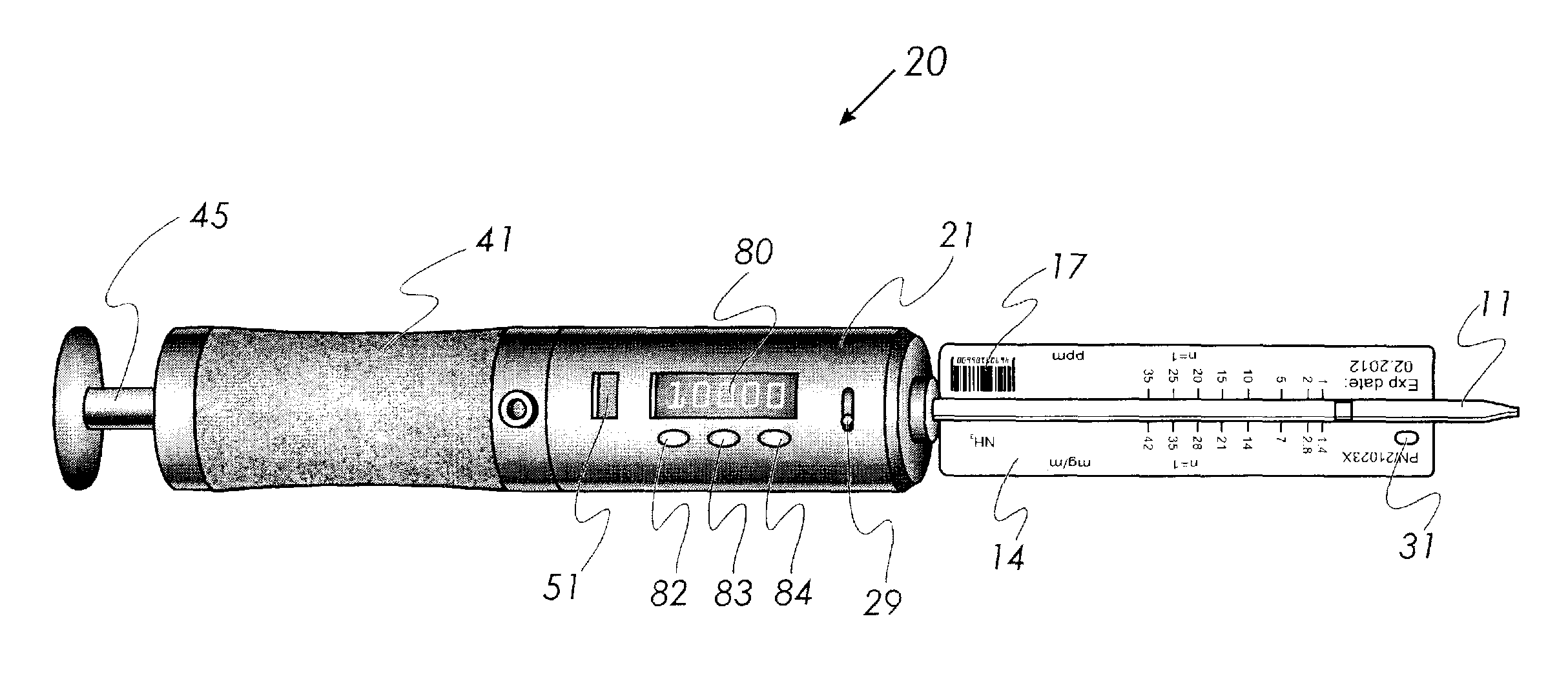
The patent allows for the use of gas detector tubes in two ways: visually and optic-electronically. This provides a more accurate and flexible way to use the gas detector tubes.

Problems solved by technology

Currently, detector tubes relying on measurement of the intensity or density of the generated color are not used because of difficulties in creating an appropriate set of color standards to indicate the concentration of the gas.
As such, the scales are of poor resolution and, more recently, the scales printed directly on the surface of the tube.
The drawback of the known art is that such detector tubes cannot be read by electronic device because of the concentration lines, concentration amounts, and other marks on the tubes obstructing optical reading of the length of stain.
There is a significant drawback of the tubes manufactured to be read by electronic reader only; they may not also by read visually.
Such devices however are highly specific and cannot be read without specialized electronic means.

Method used


Image

  • System for visual and electronic reading of colorimetric tubes
  • System for visual and electronic reading of colorimetric tubes
  • System for visual and electronic reading of colorimetric tubes

Examples


example

Gas Detector Tubes and Gas Detector Tube Reader

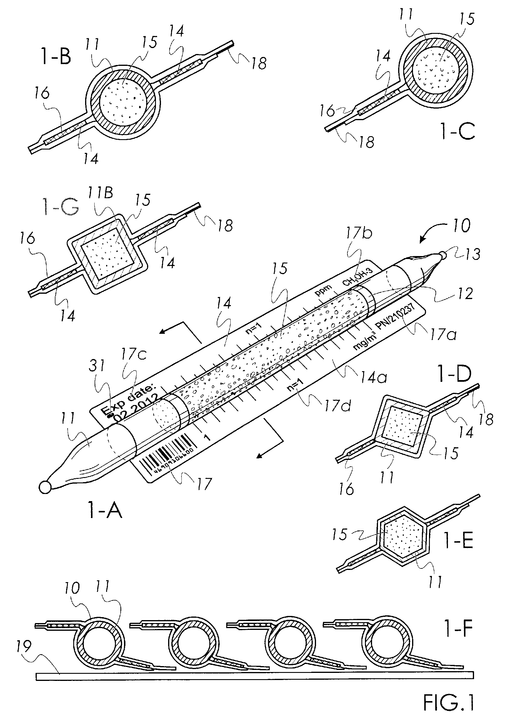
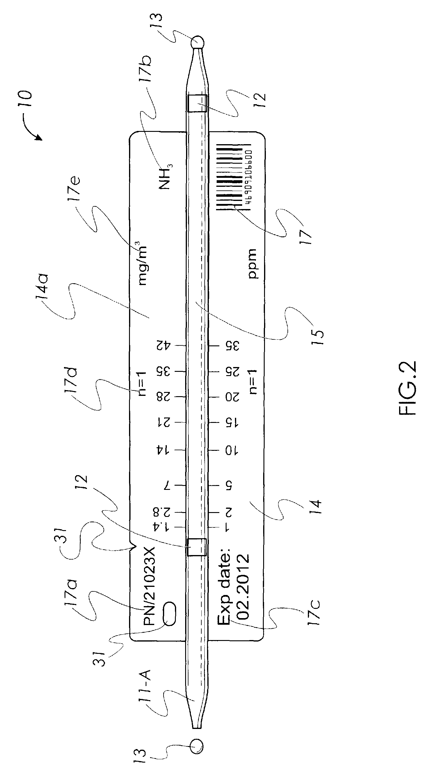
[0080]Embodiments of the gas detector tubes 10 are shown on FIGS. 1A-E and FIG. 2. The gas detector tubes 10 comprise a sealed transparent tube 11, a chemical reagent 15 capable of a colorimetric reaction with a gaseous chemical compound within the sealed transparent tube 11, at least one elongated extension 14 extending from the tube 11, and at least one length of stain measurement scale on the extension 14.

[0081]The embodiments of FIGS. 1A to 1E depict various cross-sectional areas of the transparent tube 11 including circular in FIGS. 1-B and 1-C, and polygon in FIG. 1-D and FIG. 1-F. The surface of the tube 11 is clean and clear of markings in the area of the reagent 15 for visual or electronic reading of the length of stain. The gas detector tube 10 comprises a transparent tube 11 comprising at least one inert material such as glass, acrylic, polycarbonates, copolymers of polyethylene and polypropylene, polyesters, etc. The extensi...


PUM

PropertyMeasurementUnit
angleaaaaaaaaaa
angleaaaaaaaaaa
altitudeaaaaaaaaaa

Abstract

Gas detector tubes may be used to determine a concentration of target gases in air. The gas detector tubes described may be read either by and optical reader or visually by the user. A gas detector tube reader having an optical reader capable of reading a length of stain, a color change and color density of a reagent in a gas detector tube. The gas detector tube may further comprise sensors for measuring the environmental conditions during sampling.

Description

RELATED PATENT APPLICATIONS[0001]This patent application claims priority under 35 U.S.C. §119 to U.S. Provisional Patent Application No. 61 / 380,582 filed on Sep. 7, 2010 which is hereby incorporated by reference in its entirety.FIELD OF THE INVENTION[0002]The invention relates to gas detector tubes and an apparatus for sampling. Embodiments of the apparatus are capable of detecting and determining an approximate concentration of at least one component of a gas mixture. Embodiments of the apparatus comprise a system for colorimetric detection of certain components of a gas by color change of a chemical reagent. The resulting color change may be optically measured as a length-of-stain that is proportional to the reacted quantity of the target gas or as a level of color difference between unchanged and changed by chemical reaction color. In embodiments of the gas detector tube, the length of stain and / or color change may be determined visually or electro-optically.BACKGROUND OF THE INV...

Claims


Application Information

Patent Timeline
Patent Type & Authority Patents(United States)
IPC IPC(8): G01N30/96G01J1/48G01B11/14G01N31/00
CPCG01N21/783
Inventor TRUEX, BRYAN I.MIHAYLOV, GUEORGUI
Owner NEXTTEQ
Learn More