
Device for measuring the body core temperature

a body core temperature and measurement device technology, applied in the field of body core temperature measurement devices, can solve the problems of undesirable or inability to tolerate inaccuracy due to conventional peripheral measurement methods, inability to readily determine the temperature of the body by conventional temperature measurement methods, and poor reproducibility, so as to achieve simple, accurate and reproducible body core temperature, and high level of wearing comfort

Active Publication Date: 2013-08-20
DRAGERWERK AG
View PDF64 Cites 6 Cited by
  • Summary
  • Abstract
  • Description
  • Claims
  • Application Information

AI Technical Summary

Benefits of technology

[0019]Thus, the object of the present invention is to provide a device that makes possible a simple, accurate and reproducible body core temperature measurement with a high level of wearing comfort and avoids the drawbacks of the above-mentioned state of the art.

Problems solved by technology

Such devices can be used wherever the body core temperature is to be determined, but inaccuracies due to conventional peripheral measuring methods are undesirable or cannot be tolerated.
However, it cannot be readily determined by conventional temperature measuring methods.
These deviations are either difficult to calculate, lead to poorly reproducible results or show highly sensitive dependences on various extraneous effects.
This considerably restricts the freedom of movement, and this method is therefore inherently ruled out for the monitoring of active mission personnel.
Rectal measurement may be dangerous when full freedom of movement is required at the same time.
In addition, both are ruled out for the monitoring of active mission personnel due to the restrictions associated with them in terms of the freedom of movement.
However, these arrangements are suitable for monitoring fever only and have the drawback that the body temperature is measured at a relatively great distance from the core.
However, this method likewise fails to open up a possibility of measuring the body core temperature.
A second requirement imposed on the position of the double temperature sensor is that the thinnest possible fat layer or no fat layer shall be located between the sensor and the core zone to be measured, because the strong insulating action of fatty tissue may hinder such measurements of the body core temperature as a whole or make them inaccurate.
However, this placement may sometimes be associated with a considerable loss of wearing comfort.
Placing the double temperature sensor in the head area is ruled out in other cases because of insufficient space.
This process and the sensor are, however, substantially more complicated than a simple double temperature sensor.

Method used


Image

  • Device for measuring the body core temperature
  • Device for measuring the body core temperature
  • Device for measuring the body core temperature

Examples


Embodiment Construction

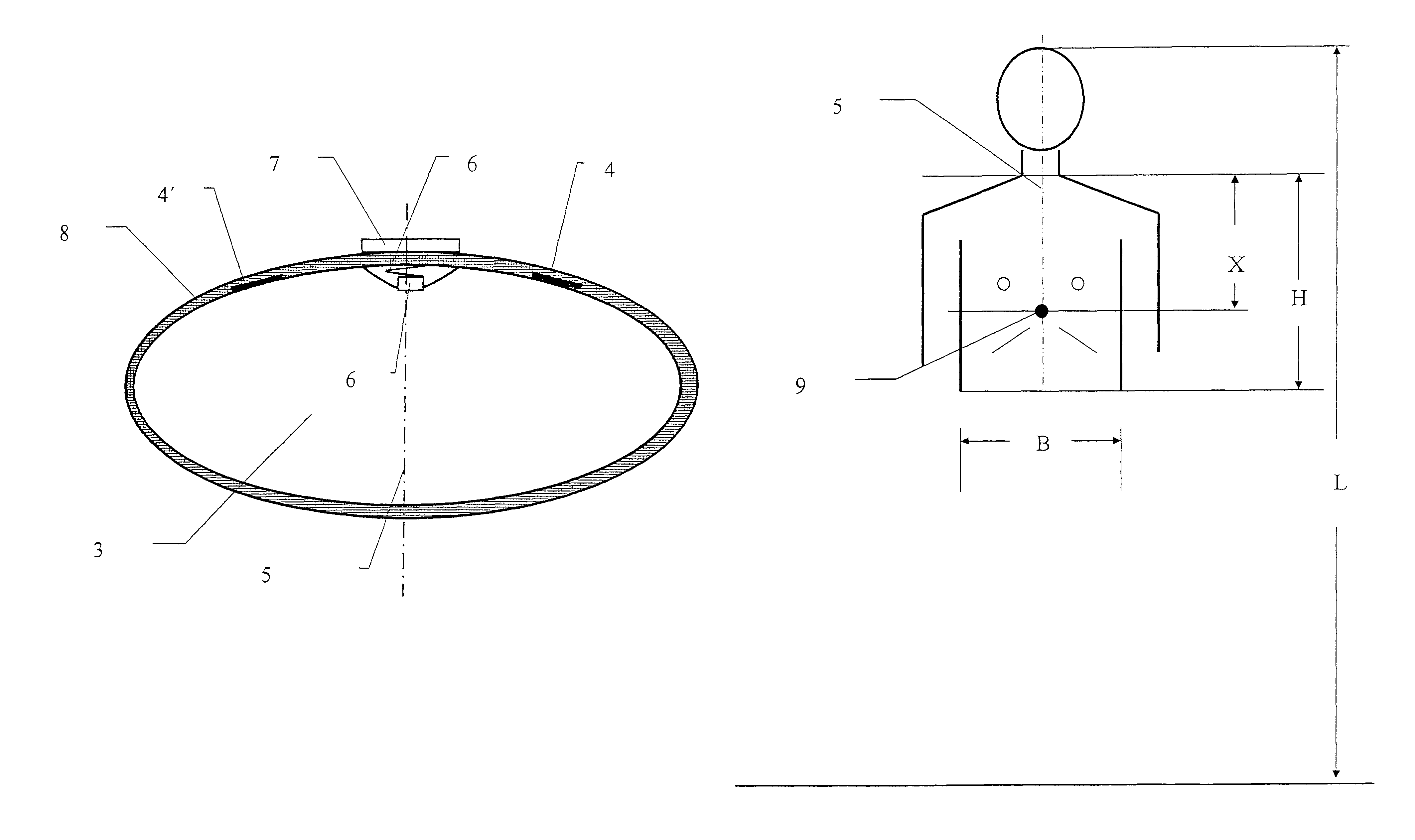
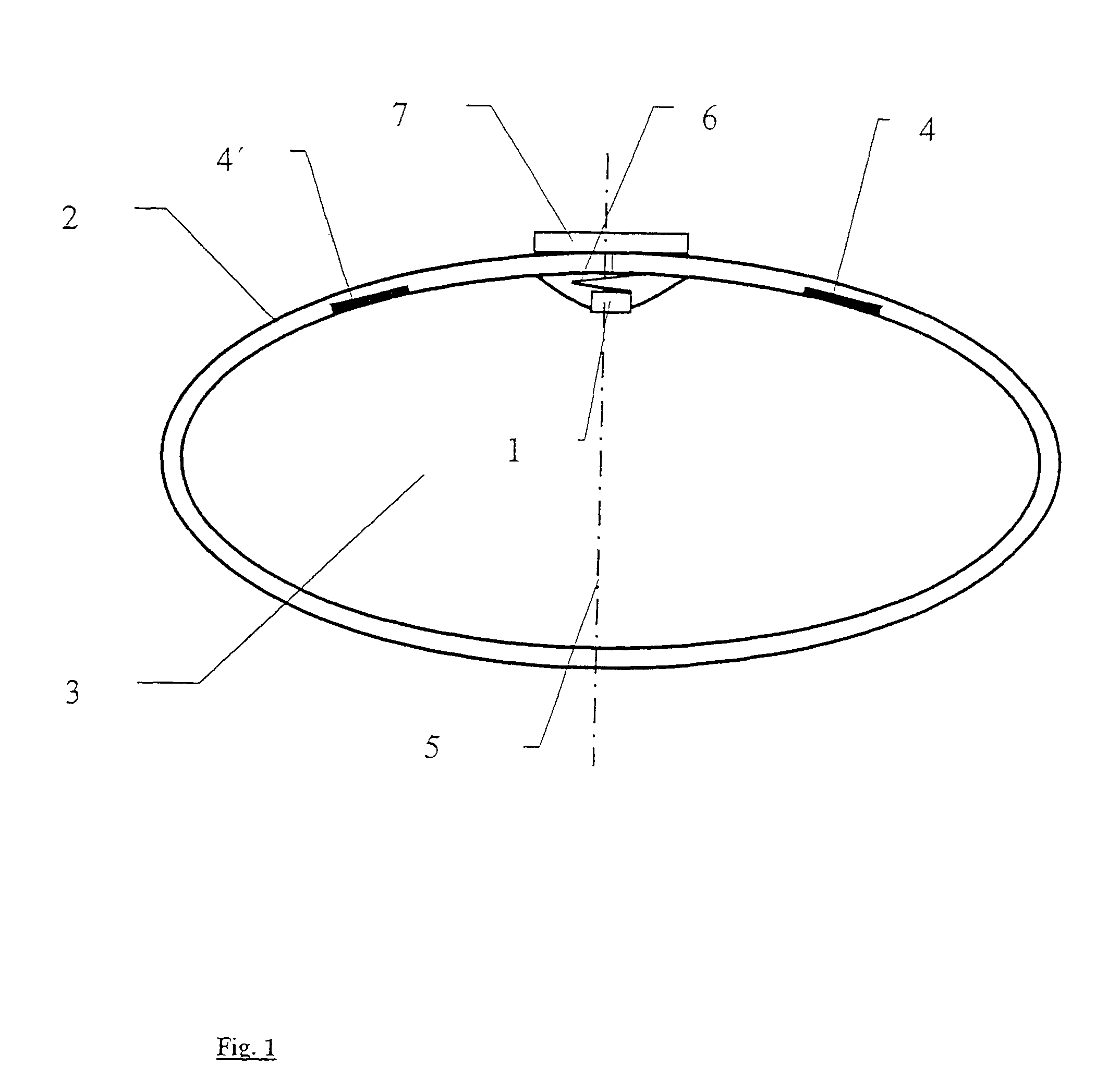
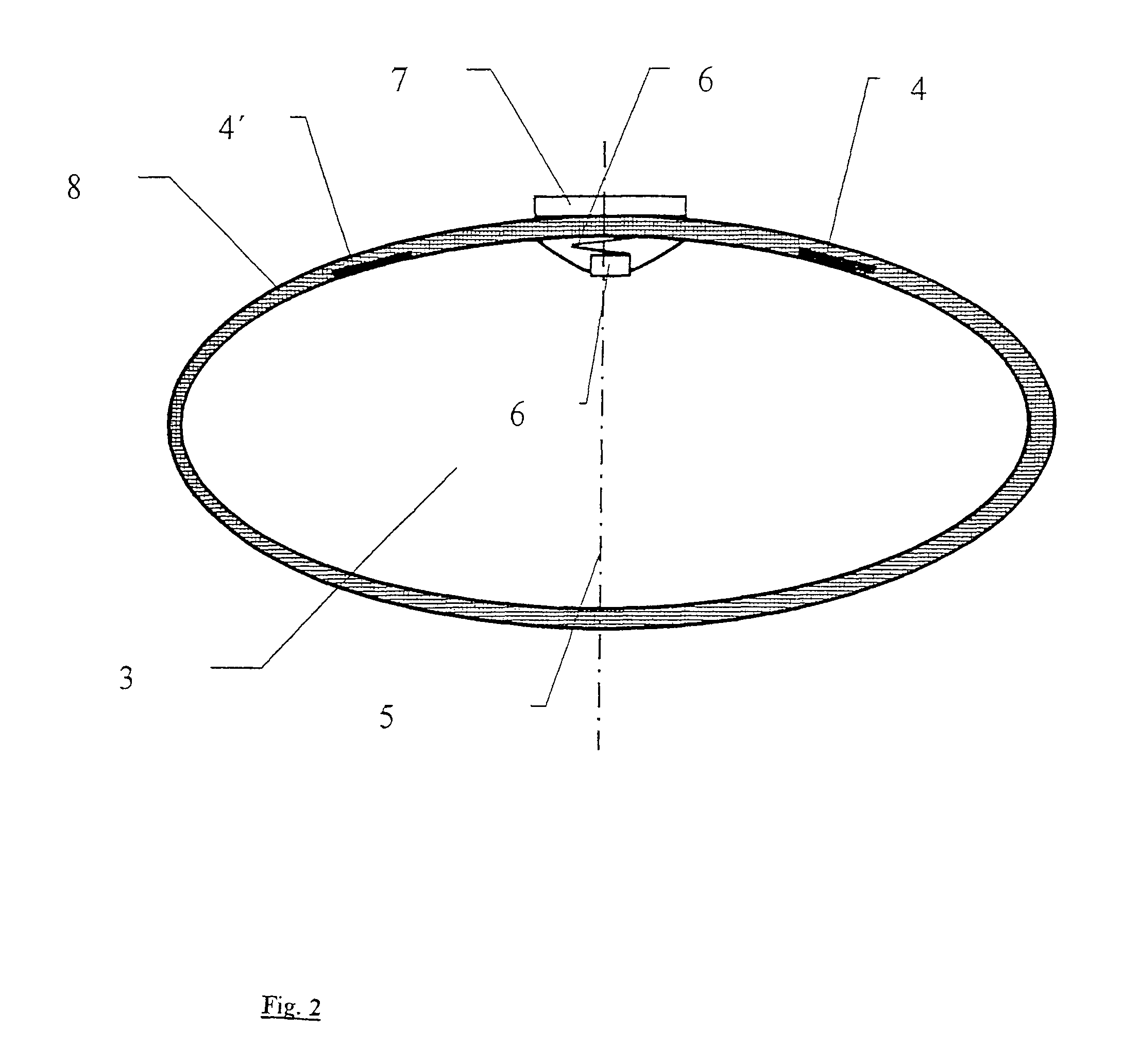
[0047]Referring to the drawings in particular, FIG. 1 illustrates the arrangement according to the present invention of a double temperature sensor 1 on a chest belt 2. The chest belt 2 is tightened around the upper body 3 of a person. In the terminology of the present invention, it is a means for wrapping firmly around the upper body. The level of the chest belt 2 is set by the user such that it is placed somewhat below the chest, but it still lies fully over the ribs. Two electrodes 4, 4′ acting as sensors for measuring the pulse rate are placed on the chest belt. These are placed symmetrically on both sides laterally from the center line 5 of the body. With a fastening element, which comprises essentially a spring 6, the double temperature sensor 1 is fastened to the chest belt 2 in the middle between the two electrodes 4, 4′, which act as pulse sensors. The double temperature sensor 1 is pressed by the spring 6 firmly onto the upper body 3, even though there is a rather great di...


PUM

PropertyMeasurementUnit
pressureaaaaaaaaaa
pressureaaaaaaaaaa
pressing pressureaaaaaaaaaa

Abstract

A device for measuring the body core temperature of a person contains a structure for firmly wrapping around the upper body of the person. A double temperature sensor is connected with the structure for wrapping around the upper body such that the double temperature sensor is pressed elastically onto the upper body in the state in which it is put on in the area of the sternum. The device for measuring the body core temperature is suitable for the integration of a body core temperature measurement in clothing or chest belt systems.

Description

CROSS REFERENCE TO RELATED APPLICATIONS[0001]This application claims the benefit of priority under 35 U.S.C. §119 of DE 10 2004 028 359.1 filed Jun. 11, 2004, the entire contents of which are incorporated herein by reference.FIELD OF THE INVENTION[0002]The present invention pertains to a device with double temperature sensor for measuring the body core temperature of a person.BACKGROUND OF THE INVENTION[0003]Such devices can be used wherever the body core temperature is to be determined, but inaccuracies due to conventional peripheral measuring methods are undesirable or cannot be tolerated. Devices according to the present invention are especially suitable for monitoring firemen and rescue personnel, who are exposed to physical strains at extreme temperatures. Strain limits can be set and mission decisions can be made with the data thus obtained.[0004]Another field of use is represented by patient monitoring in medical applications. In particular, the monitoring of diseases associa...

Claims


Application Information

Patent Timeline
Patent Type & Authority Patents(United States)
IPC IPC(8): G01K1/02G01K1/16G01K1/14G01D11/30A61B5/01A61B5/0205G01K1/00G01K1/20G01K7/42G01K13/00G01K17/00
CPCA61B5/6831G01K1/14G01K1/20G01K7/42G01K13/002G01K17/00G01K13/20A61B5/0205
Inventor KOCH, JOCHIM
Owner DRAGERWERK AG
Learn More