Fiber optic drop cable assembly for deployment on building walls

a technology of fiber optic cables and drop cables, applied in the field can solve the problems of no practical way to internally route cabling through the infrastructure, time-consuming and expensive deployment, and inability to provide the telecommunication performance of fiber optic cables,

Inactive Publication Date: 2013-08-20
CORNING OPTICAL COMM LLC
View PDF23 Cites 3 Cited by
  • Summary
  • Abstract
  • Description
  • Claims
  • Application Information

AI Technical Summary

Problems solved by technology

However, for certain buildings, and in particular older buildings, such deployment can be time consuming and expensive.
Further, in many older buildings, there may actually be no practical way to internally route cabling through the infrastructure.
However, this approach is expensive and does not provide the telecommunication performance offered by fiber optic cables.
However, such a solution is made very difficult by the bending tolerances of typical fiber-based drop cables, and is complicated by the need to ground the steel messengers used to offload mechanical loads and strains that would otherwise be borne by the fiber optic cable.

Method used


Image

  • Fiber optic drop cable assembly for deployment on building walls
  • Fiber optic drop cable assembly for deployment on building walls
  • Fiber optic drop cable assembly for deployment on building walls

Examples


Embodiment Construction

[0032]Reference is now made to preferred embodiments of the invention, examples of which are illustrated in the accompanying drawings. Whenever possible, the same or similar reference numbers and symbols are used throughout the drawings to refer to the same or similar parts.

[0033]Cartesian X-Y-Z coordinates are referenced in certain Figures for the sake of reference, with the “vertical” direction being the Z-direction and the direction of gravity.

[0034]Term “axially arranged” in connection with the dielectric messenger discussed below means substantially along the direction of the central axis, and not necessary coaxial with the central axis.

Fiber Optic Drop Cable Assembly

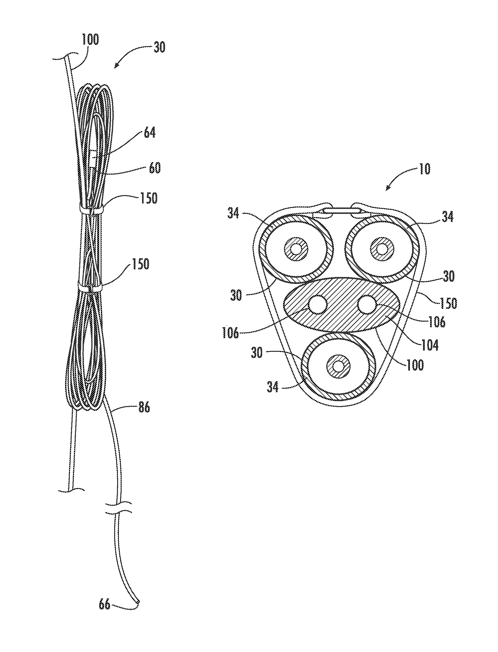
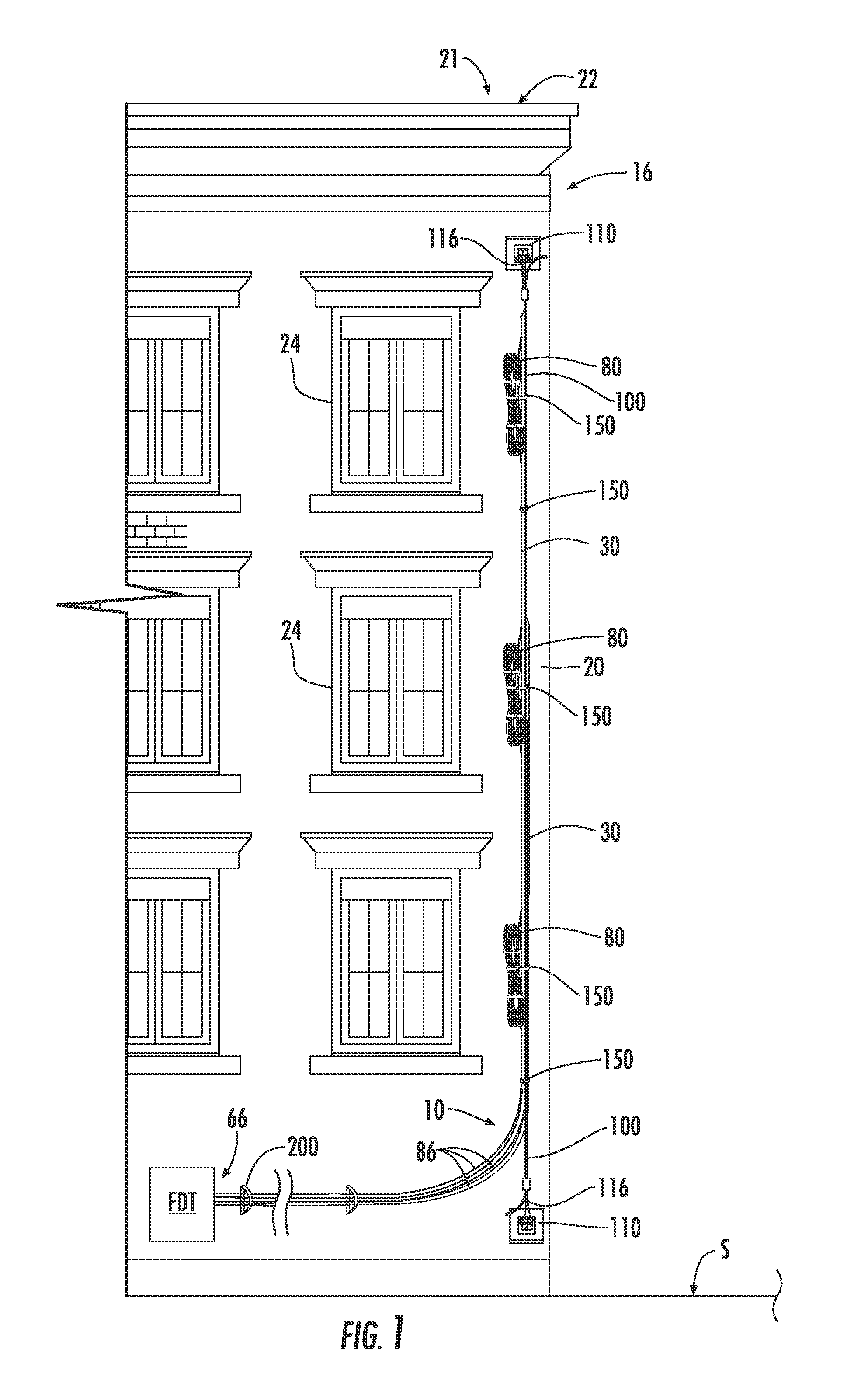
[0035]FIG. 1 is a schematic front-on view of an example embodiment of the fiber optic assembly (“assembly”) 10 as shown deployed on a building 16 on an outside wall 20. Building 16 includes a roof 21 that has a “knee wall”22, and wall 20 includes openings 24. Openings 24 may be, for example, windows, vents, holes, ...


PUM


Abstract

A fiber optic drop cable assemblies and methods for deploying the same on a wall of a building are disclosed. The assembly includes a messenger member and a plurality of fiber optic cables each having a length, a connectorized end, and containing at least one optical fiber, the fiber optic cables being removably secured to the messenger member at a plurality of locations. The fiber optic cables are secured to the messenger member at a plurality of locations that correspond to select building locations, such as windows, through which the cable can be fed into the building.

Description

PRIORITY APPLICATION[0001]This application claims the benefit of U.S. Provisional Application Ser. No. 61 / 185,433 filed on Jun. 9, 2009, the entire contents of which are incorporated by reference herein.BACKGROUND ART[0002]1. Technical Field[0003]The present invention relates generally to fiber optic cables, and in particular relates to fiber optic drop cable assemblies for deployment on building walls.[0004]2. Technical Background[0005]Fiber optic communications has experienced explosive growth. In just a few years, the transmission of communication signals for voice, video, data, and the like has soared, and more growth is planned as fiber optic communication technology improves and networks expand to provide greater access.[0006]Fiber optic cables are the backbone of fiber optic communication systems. Fiber optic cables carry optical fibers and other cable elements, which are protected from the external environment by an external jacketing.[0007]Fiber optic cables that carry opti...

Claims


Application Information

Patent Timeline
Patent Type & Authority Patents(United States)
IPC IPC(8): G02B6/44
CPCG02B6/4466G02B6/4457G02B6/4471G02B6/475
Inventor ABERNATHY, GEORGE C.CASSELL, DANIEL A.HARVEY, GERRY J.LAIL, JIMMY E.TEMPLE, JR., KENNETH D.
Owner CORNING OPTICAL COMM LLC
Why Eureka
Try Eureka