Gas turbine engine geared architecture axial retention arrangement

a technology of axial retention and geared architecture, which is applied in the direction of power plant arrangement/mounting, non-positive displacement fluid engine, liquid fuel engine components, etc., can solve the problems of undesirable movement and the inability of the support structure to provide the desired axial retention of the geared architectur

Active Publication Date: 2013-08-27
RAYTHEON TECH CORP
View PDF13 Cites 27 Cited by
  • Summary
  • Abstract
  • Description
  • Claims
  • Application Information

AI Technical Summary

Benefits of technology

[0011]In a further embodiment of any of the above, threaded fasteners removably s

Problems solved by technology

Extreme engine events such as fan blade loss or failure of fan shaft bearing supports may encourage significant axial movement of the geared architecture and the fan, relative to other portions of th

Method used


Image

  • Gas turbine engine geared architecture axial retention arrangement
  • Gas turbine engine geared architecture axial retention arrangement
  • Gas turbine engine geared architecture axial retention arrangement

Examples


Embodiment Construction

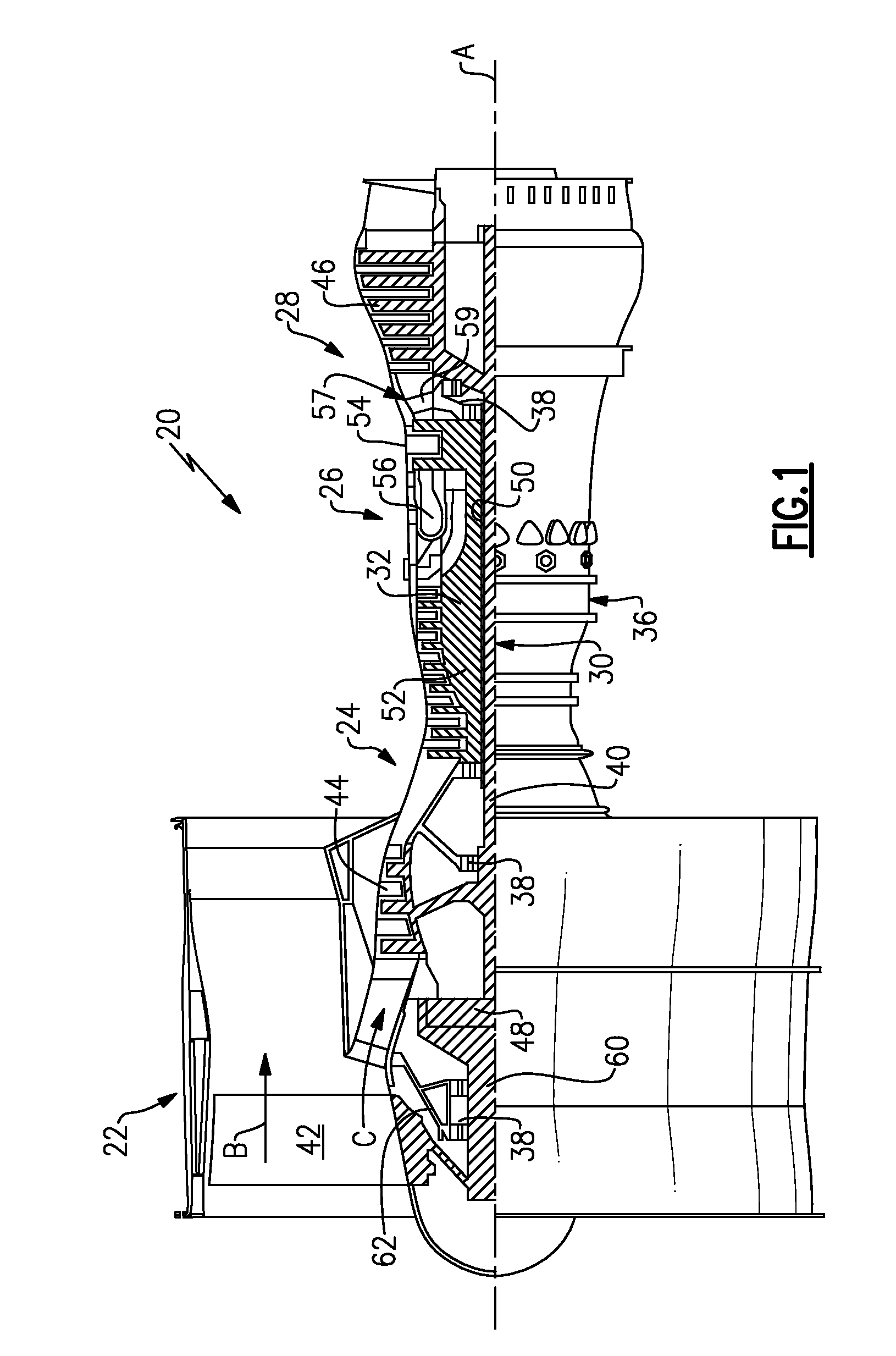
[0035]FIG. 1 schematically illustrates a gas turbine engine 20. The gas turbine engine 20 is disclosed herein as a two-spool turbofan that generally incorporates a fan section 22, a compressor section 24, a combustor section 26 and a turbine section 28. Alternative engines might include an augmentor section (not shown) among other systems or features. The fan section 22 drives air along a bypass flowpath B while the compressor section 24 drives air along a core flowpath C for compression and communication into the combustor section 26 then expansion through the turbine section 28. Although depicted as a turbofan gas turbine engine in the disclosed non-limiting embodiment, it should be understood that the concepts described herein are not limited to use with turbofans as the teachings may be applied to other types of turbine engines including three-spool architectures.

[0036]The engine 20 generally includes a low speed spool 30 and a high speed spool 32 mounted for rotation about an e...


PUM

PropertyMeasurementUnit
Lengthaaaaaaaaaa
Structureaaaaaaaaaa

Abstract

A support assembly for a geared architecture includes an engine static structure. A flex support is secured to the engine static structure and includes a bellow. A support structure is operatively secured to the flex support. A geared architecture is mounted to the support structure. First members are removably secured to one of the engine static structure and the flex support and second members are removably secured to the support structure. The first and second members are circumferentially aligned with one another and spaced apart from one another during a normal operating condition. The first and second members are configured to be engageable with one another during an extreme event to limit axial movement of the geared architecture relative to the engine static structure.

Description

[0001]This application is a continuation application of U.S. patent application Ser. No. 13 / 435,353, which was filed on Mar. 30, 2012.BACKGROUND[0002]This disclosure relates to limiting axial movement of a geared architecture within a turbomachine during an extreme event.[0003]Turbomachines, such as gas turbine engines, typically include a fan section, a turbine section, a compressor section, and a combustor section. Turbomachines may employ a geared architecture connecting the fan section and the turbine section.[0004]Support structures are used to hold the geared architecture within the turbomachine. The support structures may be relatively compliant to accommodate some movement of the geared architecture relative to other portions of the turbomachine. Extreme engine events such as fan blade loss or failure of fan shaft bearing supports may encourage significant axial movement of the geared architecture and the fan, relative to other portions of the turbomachine. These movements a...

Claims


Application Information

Patent Timeline
IPC IPC(8): F01D15/12F01D25/18F03D11/02A47C7/74B63H1/00F16H57/04
CPCF01D25/16F02C7/20B64D27/26F02C7/36F05D2220/36Y10T29/49318B64D2027/266F01D21/045F05D2260/40311
Inventor COFFIN, JAMES B.PESCOSOLIDO, ALESSIO
Owner RAYTHEON TECH CORP
Why Eureka
Try Eureka