
Arrow vane airfoil

Inactive Publication Date: 2013-09-03
KUHN TODD DR
View PDF7 Cites 6 Cited by
  • Summary
  • Abstract
  • Description
  • Claims
  • Application Information

AI Technical Summary

Benefits of technology

This patent aims to provide better arrow vanes for compound arrows, crossbow arrows, and traditional arrows that can improve flight characteristics over traditional vanes. The invention allows for the use of flat, planar vanes that can be easily applied to a traditional arrow shaft and converted into a three-dimensional airfoil that provides laminar airflow and aerodynamic lift to the arrow. The invention also includes a compound bending of the planar vanes to provide structural rigidity and reduce fluttering during flight, resulting in increased arrow speeds and accuracy. Additionally, the invention includes a design with a very diminutive profile that allows the vane to be shot down a crossbow track without interference. Overall, this patent provides improvements in the design of arrow vanes to enhance the performance of arrows.

Problems solved by technology

However, due to decreased spacing between the vanes, the helical and offset mounted vanes often interfere with the arrow rest of the bow when the arrow is being shot.
This interference is known to cause the arrow to change direction after it is shot and can result in the arrow wobbling during flight, which can result in poor target accuracy and shorter flight distance.
Additionally, helically oriented and off-set oriented vanes present a similar problem when shot down a rigid, planarcrossbow arrow track.
The rigid, planar track, will not physically allow the passage of these helically oriented and off-set oriented vanes as the vanes interfere with the planar nature of the crossbow arrow track which is a machined or molded track in which the arrow vane is slipped and the arrow can miss its' target.
However, these vanes are generally flat planar vanes with little or no curved aerodynamic surface.
However, these products have not been commercially successful due to the planar surface.
During flight, these planar vanes with molded kickers and “airfoil” shapes flex and then flutter uncontrollably during flight due to the great amount of turbulent airflow over their surfaces.
These modified vanes, which increase aerodynamic drag exponentially, slow the arrow and result in less than desirable results.
The problem here is that most arrows do not allow for a separate attachment shaft with vane.
So this prior art would not be useful to be used with most existing arrows.

Method used


Image

  • Arrow vane airfoil
  • Arrow vane airfoil
  • Arrow vane airfoil

Examples


Embodiment Construction

[0034]Before explaining the disclosed embodiments of the present invention in detail it is to be understood that the invention is not limited in its applications to the details of the particular arrangements shown since the invention is capable of other embodiments. Also, the terminology used herein is for the purpose of description and not of limitation.

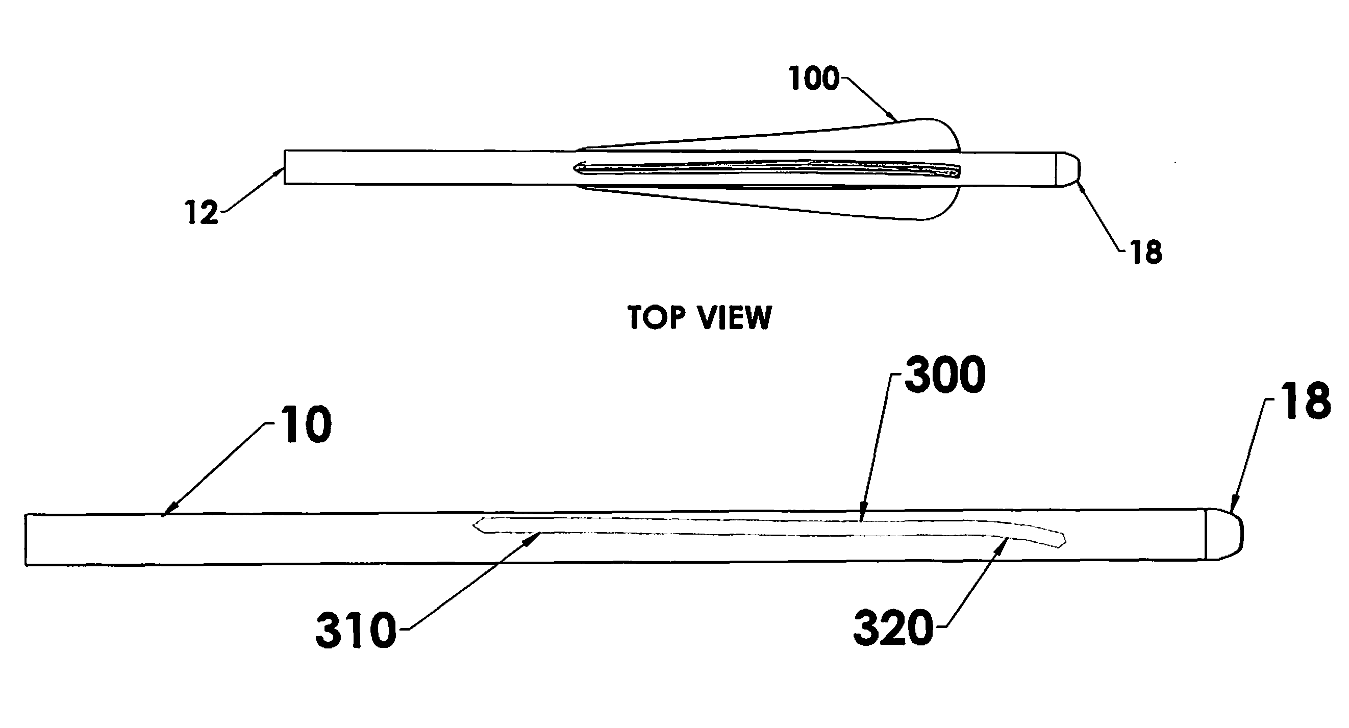
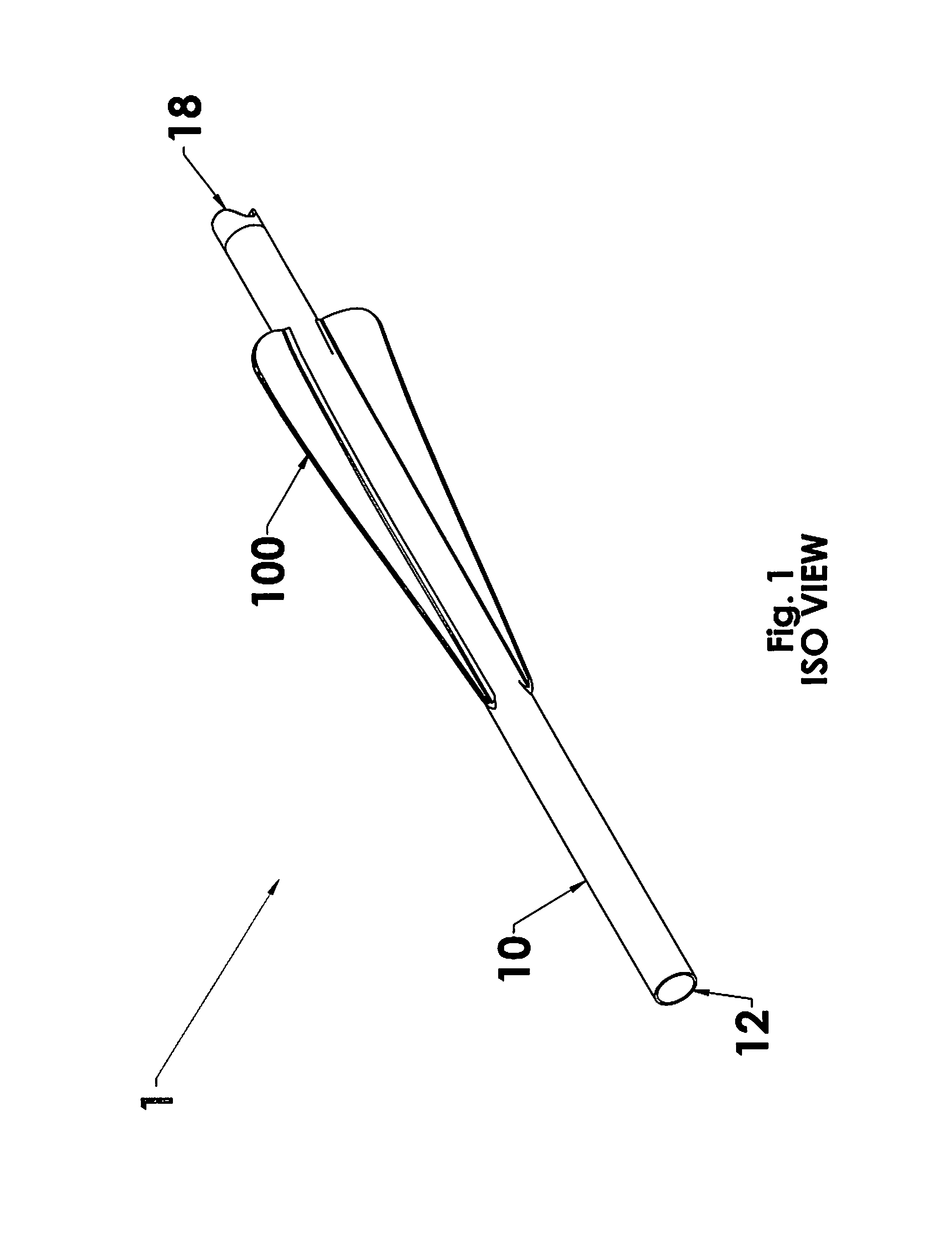
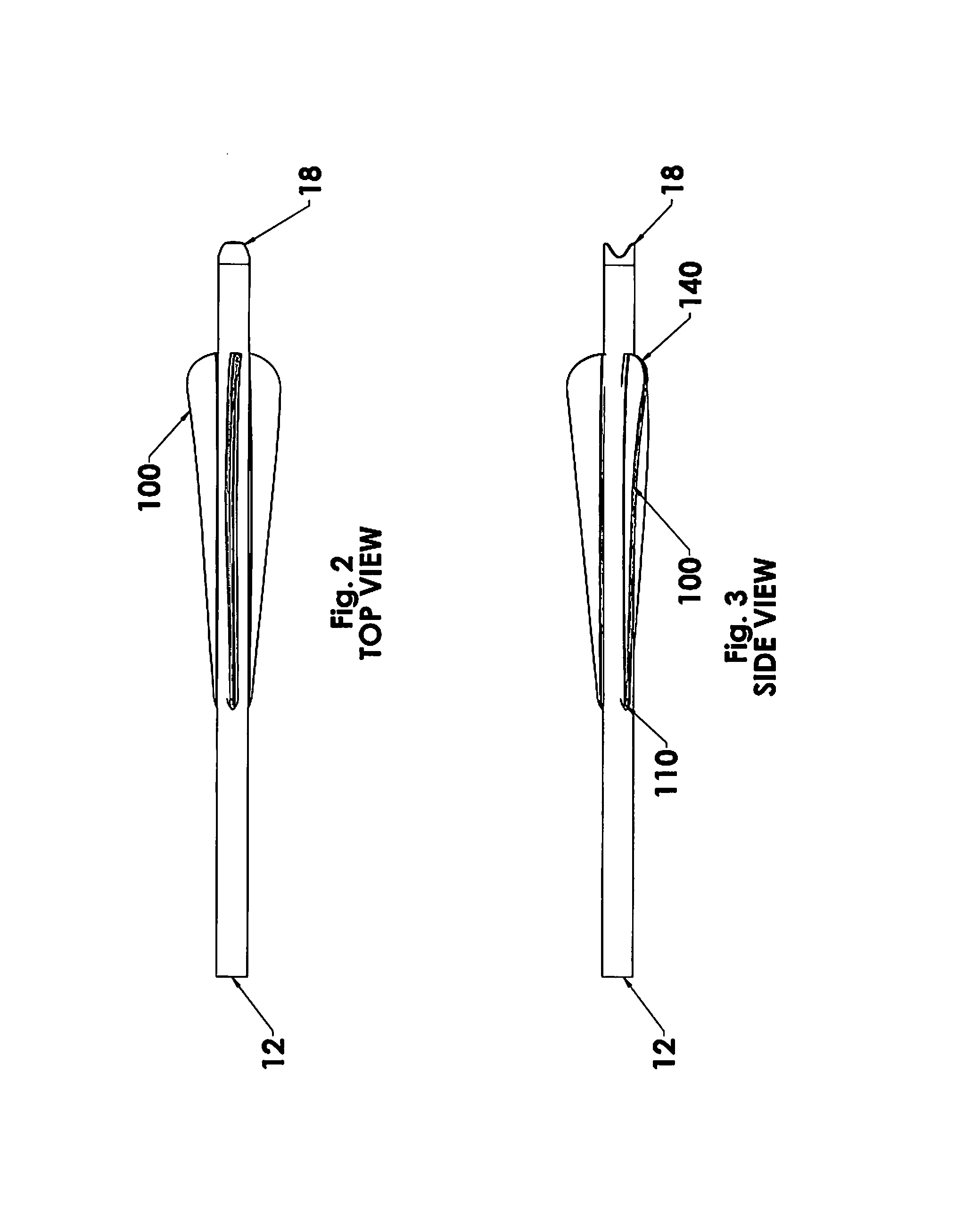
[0035]The components labeled in the figures are listed below.[0036]1. Arrow with novel aerodynamic airfoil vanes.[0037]10. shaft of arrow[0038]12. tip end of arrow[0039]18. nock end of arrow[0040]100. aerodynamic airfoil vane(s)[0041]110. leading edge of vane(s)[0042]140. trailing edge of vane(s)[0043]200. bend creating fletching clamp[0044]210. clamp handle[0045]220. clamp handle[0046]230. front side housing[0047]240. rear side housing[0048]250. groove for vane[0049]252. straight channel in groove[0050]255. bent channel portion in groove[0051]300. base of bent vane on shaft[0052]310. generally straight portion[0053]320. bent portio...


PUM


Abstract

Arrow vanes, devices and methods for improving arrow vane airfoils for compound arrows, crossbow arrows and traditional arrows, which improves flight characteristics over traditionally manufactured, configured and / or applied vanes. Compound bends in the base of the vanes can be done by clamping the vanes in a channel having a generally straight portion and a generally bent portion. The bent portion can have a helical right bend or a helical left bend. A fletching jig can be used to glue the compound bent bases of the vanes to sides of an arrow shaft.

Description

FIELD OF INVENTION[0001]This invention relates to archery arrow vanes, and more particularly to arrow vanes, devices and methods for improving arrow vane airfoils for compound arrows, crossbow arrows and traditional arrows, which improves flight characteristics over traditionally manufactured, configured and / or applied vanes.BACKGROUND AND PRIOR ART[0002]In order to increase rotation of an arrow in flight, vanes have been attached at helical and / or offset orientations to the arrow shaft. However, due to decreased spacing between the vanes, the helical and offset mounted vanes often interfere with the arrow rest of the bow when the arrow is being shot. This interference is known to cause the arrow to change direction after it is shot and can result in the arrow wobbling during flight, which can result in poor target accuracy and shorter flight distance. See for example, U.S. Pat. No. 4,867,426 to Mellick.[0003]Additionally, helically oriented and off-set oriented vanes present a simi...

Claims


Application Information

Patent Timeline
IPC IPC(8): F42B6/06
CPCF42B6/06
Inventor KUHN, TODD A.
Owner KUHN TODD DR
Learn More